background image

2. 

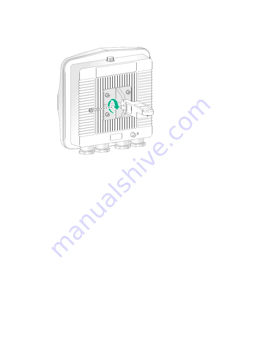
Use an M6 screw to attach the articulating arm to the AP bracket. 

Figure 9 Attaching the articulating arm to the AP bracket 


Pole-mounting the AP 

Worm-gear clamps and a wall/pole bracket are required to pole-mount the AP. The worm-gear clamp 
provided with the AP is applicable to poles with a diameter of 65 to 90 mm (2.56 to 3.54 in). If the 
diameter of the pole is not in the range, prepare worm-gear clamps yourself. 

You can mount the AP on a vertical or horizontal pole. 

Mounting the AP on a vertical pole 

1. 

Pass the worm-gear clamps through the mounting holes in the wall/pole bracket. Use the 
worm-gear clamps to secure the wall/pole bracket to the vertical pole and fasten the nuts. 

Summary of Contents for SFP-GE-LH40-SM1310

Page 1: ...8 Attaching the AP bracket to the AP 8 Pole mounting the AP 9 Wall mounting the AP 11 Positioning the AP 13 Connecting IoT access units 14 Connecting the AP to the power source 14 Connecting the PoE power supply 15 Connecting a power injector 15 Labeling cables 17 Verifying the installation 17 Powering on the AP 17 Verifying the network connection 18 Appendix A Technical specifications 19 Appendix...

Page 2: ...adars radio stations or electrical substations unstable voltage heavy vibration and loud noise Dry without any leakage dripping or dew Away from inflammable and explosive substances More than 5 m 16 40 ft away from 3G and 4G base stations and antennas The AP uses built in directional antennas For the optimal coverage make sure the installation height does not exceed 5 m 16 40 ft and no obstacles e...

Page 3: ...f a piece of steel tube it must have a wall thickness of a minimum of 3 5 mm 0 14 in Weld the yellow and green grounding cable of the AP onto the grounding conductor and use anti erosion treatment on the welding joint With a cross section area of a minimum of 6 mm2 0 01 in2 the grounding cable must be as short as possible and must not be coiled Make sure the grounding terminals of all the lightnin...

Page 4: ...ends of the tube Installation accessories Figure 1 lists the installation accessories provided with the AP Figure 2 lists the installation accessories to be prepared by users Figure 1 Installation accessories provided with the AP Figure 2 Installation accessories to be prepared by users Installation tools and equipment When installing the AP you might need the following tools Prepare these tools a...

Page 5: ...4 Figure 3 Installation tools and equipment ...

Page 6: ...p of a building make sure the AP does not project beyond the sides of the building To avoid high temperature caused by exposure to the sun install the AP in a place without or with less direct sunlight and take protection measures if necessary Pre installation tasks Before installing an AP perform the following tasks Connect the AP to the power source and the network Examine the LED to verify that...

Page 7: ...6 Installation flowchart Figure 4 Installation flowchart ...

Page 8: ...epare one yourself To connect the grounding cable to the AP 1 Attach the ring terminal to the grounding cable Figure 5 Attaching the ring terminal to the grounding cable 2 Attach the ring terminal of the grounding cable to the grounding screw on the AP Connect the other end of the grounding cable to the earth Figure 6 Attaching the grounding cable to the AP Connecting Ethernet cables IMPORTANT Onl...

Page 9: ...ght adapter and sealing nut Figure 7 Connecting an Ethernet cable to the AP Installing the AP Attaching the AP bracket to the AP CAUTION Keep the protective vent port closed on the AP Do not open it Before mounting the AP on a wall or pole attach the AP bracket to it To attach the AP bracket to the AP 1 Align the mounting holes in the AP bracket with the screw holes in the rear of the AP Use M5 sc...

Page 10: ...mp provided with the AP is applicable to poles with a diameter of 65 to 90 mm 2 56 to 3 54 in If the diameter of the pole is not in the range prepare worm gear clamps yourself You can mount the AP on a vertical or horizontal pole Mounting the AP on a vertical pole 1 Pass the worm gear clamps through the mounting holes in the wall pole bracket Use the worm gear clamps to secure the wall pole bracke...

Page 11: ...tached to the AP to the wall pole bracket Figure 11 Securing the AP to the wall pole bracket Mounting the AP on a horizontal pole 1 Pass the worm gear clamps through the mounting holes in the wall pole bracket Use the worm gear clamps to secure the wall pole bracket to the horizontal pole and fasten the nuts ...

Page 12: ...lating arm attached to the AP to the wall pole bracket Figure 13 Securing the AP to the wall pole bracket Wall mounting the AP No expansion bolts are provided with the AP Prepare them yourself To wall mount the AP 1 Use the AP bracket as a template to mark installation hole locations on the wall ...

Page 13: ... is too solid and slippery to locate the bit punch a notch first Each hole must have the same depth 3 Hammer expansion bolts into the holes and remove the nut and washers from each bolt Do not hammer the expansion bolts all the way into the wall and leave some space for hanging the AP Figure 15 Installing expansion bolts 4 Hang the AP on the expansion holes and fasten the screws to secure the wall...

Page 14: ...sed on the antenna radiation patterns as shown in Appendix C Antenna radiation patterns To adjust the AP to the desired elevation angle loosen the screw that attaches the articulating arm to the AP bracket To adjust the AP to the desired azimuth angle loosen the screw that attaches the articulating arm to the wall pole bracket Figure 17 Adjusting the AP ...

Page 15: ... other IoT access units must be extender IoT access units T300 X or T310 To connect IoT access units 1 Connect the IoT port on the master IoT access unit to the IoT port of the AP 2 Connect the OUT port on the IoT access unit to the IN port on another IoT access unit 3 Use a flat head screwdriver to push the slide button on each extender IoT access unit except the last one to the MID side and push...

Page 16: ...e power injectors are installed in one equipment room or maintenance hole use one power strip for all these injectors and lead in the power strip from the air switch of the AC power distribution box The PoE1 port on the dual port H3C power injector must be connected to the uplink network through the LAN1 port and PoE2 through LAN2 The following procedures use the PoE1 port as an example to connect...

Page 17: ...network through the fiber port IMPORTANT To use a pigtail fiber that does not have any protective sleeve first use liquid tight tape to encase the exposed fiber part before you connect the fiber To connect the AP to a power injector and to the network through the fiber port 1 Connect the SFP port on the AP to an Ethernet switch or access controller Figure 21 Connecting an optical fiber to the SFP ...

Page 18: ...ctly Use transparent waterproof tape to seal outdoor labels Verifying the installation After the installation is complete check the following items before powering on the AP The power source meets the power specification of the AP The AP is reliably grounded The Ethernet cables are correctly connected The cables are correctly labeled The unused ports on the AP are sealed with waterproof plugs Powe...

Page 19: ...l number of connected manual APs 1 Total number of connected auto APs 0 Total number of connected common APs 1 Total number of connected WTUs 0 Total number of inside APs 0 Maximum supported APs 3072 Remaining APs 3071 Total AP licenses 128 Local AP licenses 128 Server AP licenses 0 Remaining local AP licenses 127 Sync AP licenses 0 AP information State I Idle J Join JA JoinAck IL ImageLoad C Conf...

Page 20: ... 22 43 W with no access unit connected to it 34 43W with access units connected to it Powering option 802 3at PoE with no access unit connected to it 802 3af PoE when the AP does not have access units connected to it and operates in 1 1 MIMO radio mode Power injector When the AP has IoT access units connected to it 802 3at af PoE cannot satisfy the maximum power requirement of the AP Use a power i...

Page 21: ...re established Steady on The AP is initializing Green Flashing at 0 5 Hz The AP is starting up Flashing at 1 Hz Only the 2 4G radio has associated clients Flashing at 2 Hz The AP is upgrading the image Steady on The AP has registered on an AC but does not have any associated clients Blue Flashing at 1 Hz Only the 5G radio has associated clients Alternating between green and yellow at 1 Hz Both the...

Page 22: ...IEEE802 3u IEEE802 3af IEEE802 3at Used for connecting the AP to an uplink device for Internet or MAN access It can also receive PoE power from the uplink device It is represented by interface number GE1 0 1 in the MAP file or gigabitethernet 1 in AC configurations 10 100 1000M Ethernet port GE2 IoT IEEE802 3 IEEE802 3u An IoT interface used for connecting a downlink IoT access unit to the AP It i...

Page 23: ...nance personnel for device configuration and management only Optional transceiver modules Transceiver module fiber connector and optical fiber views To connect an SFP fiber port use an SFP transceiver module and an optical fiber with LC connectors Figure 24 SFP transceiver module Figure 25 Optical fiber with LC connectors 1 LC connector 2 Optical fiber Transceiver module specifications The transce...

Page 24: ...ns Item Specification Central wavelength 1310 nm Max transmission distance 10 km 6 21 miles Data rate 1250 Mbps Connector type Duplex LC Fiber mode SMF Fiber diameter 9 µm Transmit power 9 5 to 3 dBm Receive sensitivity 20 dBm Saturation 3 dBm Table 8 SFP GE LH40 SM1310 specifications Item Specification Central wavelength 1310 nm Max transmission distance 40 km 24 86 miles Data rate 1250 Mbps Conn...

Page 25: ...ons Item Specification Central wavelength 1550 nm Max transmission distance 40 km 24 86 miles Data rate 1250 Mbps Connector type Duplex LC Fiber mode SMF Fiber diameter 9 µm Transmit power 4 to 1 dBm Receive sensitivity 21 dBm Saturation 3 dBm ...

Page 26: ...iation patterns of the AP Central frequency Antenna radiation patterns Vertical plane Horizontal plane 2 4 GHz Table 11 5 GHz antenna radiation patterns of the AP Central frequency Antenna radiation patterns Vertical plane Horizontal plane 5 GHz Low Band 5 GHz High Band ...

Reviews: