background image


59 

Appendix B LEDs 

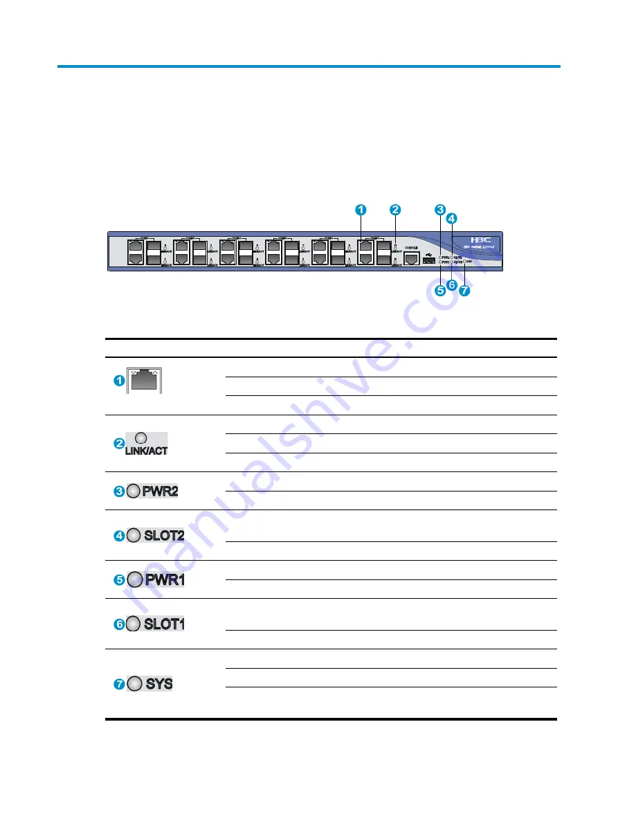
Panel LEDs 

Figure 45


F1000-A-EI LEDs 


Table 26


LED description 

LED Status 

Description 


(yellow/green) 

Off 

No link is present on the corresponding port. 

Steady green 

A 1000 Mbps link is present on the port.   

Steady yellow 

A 10/100 Mbps link is present on the port.   

 (green) 

Off 

No link is present. 

On 

A link is present.   

Flashing 

Data is being transmitted or received on the port.   

 (green) 

Off 

No power input or power module 2 is not present.   

On 

Power module 2 is operating correctly. 

 (green) 

Off 

No interface module is present in slot 2 or the 
interface module is faulty.   

On 

The interface module in slot 2 is operating correctly.   

 (green) 

Off 

No power input or power module 1 is not present.   

On 

Power module 1 is operating correctly. 

 (green) 

Off 

No interface module is present in slot 1 or the 
interface module is faulty.   

On 

The interface module in slot 1 is operating correctly.   

 (green) 

Off 

No power input or the power module is faulty.   

Slow flashing (1 Hz) 

The L1000-A is operating correctly. 

Fast flashing (8 Hz) 

The application software is being loaded, or the 
L1000-A is not working.   


Summary of Contents for SecPath L1000-A

Page 1: ...H3C SecPath L1000 A Load Balancing Device Installation Guide Hangzhou H3C Technologies Co Ltd http www h3c com Document version 5PW102 20130815 ...

Page 2: ...td All other trademarks that may be mentioned in this manual are the property of their respective owners Notice The information in this document is subject to change without notice Every effort has been made in the preparation of this document to ensure accuracy of the contents but all statements information and recommendations in this document do not constitute the warranty of any kind express or...

Page 3: ...nd conventions Convention Description Boldface Bold text represents commands and keywords that you enter literally as shown Italic Italic text represents arguments that you replace with actual values Square brackets enclose syntax choices keywords or arguments that are optional x y Braces enclose a set of required syntax choices separated by vertical bars from which you select one x y Square brack...

Page 4: ... An alert that contains additional or supplementary information TIP An alert that provides helpful information Network topology icons Represents a generic network device such as a router switch or firewall Represents a routing capable device such as a router or Layer 3 switch Represents a generic switch such as a Layer 2 or Layer 3 switch or a router that supports Layer 2 forwarding and other Laye...

Page 5: ...fferent categories of product documentation Technical Support Documents Technical Documents Provides hardware installation software upgrading and software feature configuration and maintenance documentation Products Solutions Provides information about products and technologies as well as solutions Technical Support Documents Software Download Provides the documentation released with the software ...

Page 6: ... A 13 Connecting the grounding cable 13 Installing a power module 14 Connecting interface cables 15 Connecting a copper Ethernet port 15 Connecting a fiber port 15 Connecting a power cord 16 Connecting an AC power cord 16 Connecting a DC power cord 17 Verifying the installation 17 Installing FRUs 18 Installing an interface module 18 Installing a lightning protector for a network port 19 Connecting...

Page 7: ...Verifying transceiver modules 45 Diagnosing transceiver modules 45 Troubleshooting system exceptions 46 Configuring the exception handling methods 46 Displaying the exception handling method 46 Rebooting your L1000 A 46 Troubleshooting 48 Power supply system failures 48 Fan failures 48 Configuration system failures 48 No display on the configuration terminal 49 Garbled characters on the configurat...

Page 8: ... 63 Ethernet twisted pair cable 63 Introduction 63 Making an Ethernet twisted pair cable 66 Optical fiber 66 Transceiver modules 67 LC connector 69 Precautions 69 Appendix E Cabling recommendations 71 General cabling requirements 71 Cable management requirements 71 Cabling examples 74 Index 75 ...

Page 9: ... flat and anti slip measures are in place Keep the chassis and installation tools away from walk areas Make sure the installation site is correctly grounded and lightning protection and ESD prevention are provided Only trained and qualified personnel are allowed to install or service the L1000 A Keep accessories installation tools and documentation safe Avoid bodily injury Do not touch any power p...

Page 10: ...such as interface modules put them separately in antistatic bags and install the filler panels supplied with the L1000 A If the L1000 A needs to be moved over a short distance make sure all FRUs are securely seated in slot and the screws are fastened Make sure the accessories of the L1000 A are not lost or damaged during moving Examining the installation site The L1000 A must be used indoors To en...

Page 11: ...especially when indoor relative humidity is low In the worst case electrostatic adsorption can cause communication failure Table 2 Dust concentration limit in the equipment room Substance Concentration limit particles cu m Dust particles 3 x 10⁴ No visible dust on desk in three days NOTE Dust particle diameter 5 μm The equipment room must also meet strict limits on salts acids and sulfides to elim...

Page 12: ...ipment room For more information see Temperature and humidity Always wear an ESD wrist strap and ESD cloth when touching a circuit board interface module or transceiver module Place the removed power modules and interface modules on an antistatic workbench with the face upward or put it into an antistatic bag Touch only the edges instead of electronic components when observing or moving a removed ...

Page 13: ...00 A far away from them Keep the L1000 A far away from high power radio launchers radars and equipment with high frequency or high current to make sure the EMI levels do not exceed the compliant range Use electromagnetic shielding when necessary Lightning protection To protect the L1000 A from lightning better do as follows Make sure the chassis is correctly grounded For how to ground the L1000 A ...

Page 14: ...module specifications see Power modules Installation tools The tools in the table might be used for installing the L1000 A Flat blade screwdriver Phillips screwdriver Needle nose pliers Wire stripping pliers Diagonal pliers RJ 45 crimping pliers Marker Multimeter Network cable tester Hot air blowing gun Accessories Console cable supplied with L1000 A Grounding cable supplied with L1000 A Mounting ...

Page 15: ...tallation site ESD prevention The equipment and rack are well grounded The equipment room is dust proof An anti static floor is installed and correctly grounded The humidity and temperature are at a compliant range Wear an ESD wrist strap and uniform when touching a circuit board Place the removed power modules and interface modules on an antistatic workbench with the face upward or put it into an...

Page 16: ... uninterrupted power supply UPS In case of emergency during operation switch off the external power switch Rack mounting requirements The front and rear of the rack are at least 1 m 3 28 ft away from walls or other devices The equipment room is at least 3 m 9 84 ft high and an air conditioner is installed Tools Installation accessories supplied with the L1000 A User supplied tools Reference Docume...

Page 17: ... have read Preparing for installation carefully and the installation site meets all the requirements A 19 inch rack is ready for use The rack is sturdy and securely grounded There is sufficient clearance around the rack for heat dissipation and installation No debris exists inside or around the rack Choose a correct rack mounting position for the L1000 A Make sure the heaviest device is placed at ...

Page 18: ...e L1000 A To mount the L1000 A on a workbench 1 Verify that the workbench is sturdy and well grounded 2 Place the L1000 A with bottom up and clean the round holes in the chassis bottom with dry cloth 3 Attach the rubber feet to the four round holes in the chassis bottom 4 Place the L1000 A with upside up on the workbench Installing the L1000 A in a 19 inch rack This task requires at least two peop...

Page 19: ...to the hole Figure 6 Installing cage nuts 3 Align the screw holes in one mounting bracket with the screw holes in the side panel of the chassis and use screws to attach the mounting bracket to the L1000 A as shown in Figure 7 Figure 7 Attaching the mounting brackets 4 Supporting the bottom of the L1000 A with one hand hold the L1000 A with the other hand and slide the L1000 A into the rack ...

Page 20: ...orizontally by fastening the mounting brackets to the rack with appropriate pan head screws The specifications of pan head screws must satisfy the installation requirements and rustproof treatment has been made to their surfaces Figure 9 Mounting the L1000 A to the rack ...

Page 21: ... connecting to the grounding strip 2 Peel 5 mm 0 20 in of insulation sheath by using a wire stripper and insert the bare metal part through the black insulation covering into the end of the ring terminal 3 Secure the metal part of the cable to the ring terminal with a crimper cover the joint with the insulation covering and heat the insulation covering with a blow dryer to completely cover the met...

Page 22: ...ample To install a power module 1 Face the rear panel of the L1000 A 2 Locate the slot to install the power module If a filler panel is available on the slot loosen the captive screws on the filler panel with a Phillips screwdriver and remove the filler panel 3 Keep the filler panel and install it if no power module is to be installed in the slot to prevent dust from entering the chassis 4 Correct...

Page 23: ...nd of a twisted pair cable into the port 2 Plug the other end of the twisted pair cable into the RJ 45 Ethernet port of the peer device 3 Examine the port LED status For more information about the LED status see Appendix B LEDs After you connect the L1000 A to the network execute the ping or tracert command to test network connectivity For more information about the commands see the command refere...

Page 24: ... the LC connector at one end of another fiber cable into the Tx port of the L1000 A and the LC connector at the other end to the Rx port of the peer device Figure 13 Connecting the fiber port 5 View the LINK LED after connection On means a link is present Off means no line is present Try to change the Rx and Tx ends of the fiber For more information about the LEDs see Appendix B LEDs Connecting a ...

Page 25: ...tacle 2 Use a flat blade screwdriver to fasten the screws on the plug 3 Connect the other end of the DC power cord to the DC power source Figure 15 Connecting the DC power cord Verifying the installation To ensure normal operation of the L1000 A verify the following items before you power on the L1000 A There is enough space for heat dissipation around the L1000 A The grounding cable is securely c...

Page 26: ... 2 To install an interface module 1 Locate the slot to install the interface module 2 Loosen the fastening screws on the filler panel with a Phillips screwdriver to remove the filler panel If you cannot remove the filler panel use a flat blade screwdriver to pry the filler panel up to remove it Put the removed filler panel and screws in an antistatic bag for future use Figure 16 Removing the fille...

Page 27: ...rt 3 kA Core core 15 V Core ground 350 V Installation procedure To install a lightning protector 1 Use a double faced adhesive tape to stick the lightning protector onto the L1000 A chassis and make sure it is close to the grounding screw of the L1000 A as possible 2 Measure the distance between the protector and the grounding screw of the L1000 A cut the ground wire of the protector as appropriat...

Page 28: ...otector is as short as possible to ensure its good contact with the grounding screw of the L1000 A The installed port lighting protectors are not sufficient If the L1000 A has more than one network port connected with other devices through cables outdoor install a lightning protector for each network port Connecting the AC power supply to a power strip with lightning protection CAUTION Make sure t...

Page 29: ... operating correctly Off means the circuit is damaged 2 Grounding pole detection LED red On indicates a wrong wire connection the wire is not grounded or the live line and null line are reversely connected and you need to check the power supply line 3 Power switch 4 IEC standard socket It is used to connect to the power supply in the equipment room through a power cord 5 Overload automatic protect...

Page 30: ...C Typically a PC running a terminal emulation program such as HyperTerminal on a Windows operating system is used In the following sections a PC running Windows XP HyperTerminal is used The console cable can be an 8 core shielded cable that has an RJ 45 connector at one end for connecting to the console port of the L1000 A and a DB 9 female connector at the other end for connecting to the serial p...

Page 31: ...C before connecting it to the L1000 A and when you disconnect the cable first disconnect it from the L1000 A Configuring communication parameters on the terminal 1 On the PC select Start Programs Accessories Communications HyperTerminal 2 Enter a name for the connection and click OK Figure 21 Creating a HyperTerminal connection 3 Select the serial port used to connect to the L1000 A and click OK F...

Page 32: ...3 Configuring serial port properties Table 5 Serial port properties Property Value Bits per second 9600 bps the default Data bits 8 Parity None Stop bits 1 Flow control None To restore the default settings click Restore Defaults 5 Click OK The HyperTerminal window appears ...

Page 33: ...25 Figure 24 HyperTerminal window 6 Select File Properties and then click the Settings tab Figure 25 Selecting the emulation type 7 Select VT100 or Auto detect for Emulation and click OK ...

Page 34: ...ting correctly For more information about the LED behaviors see Appendix B LEDs 2 The cooling system is working and you can hear fan rotating noise and feel air being blown out 3 The boot information on the terminal shows that the L1000 A is starting up correctly For more information see Verifying the L1000 A boot information 4 After the L1000 A starts up a prompt for pressing Enter appears Verify...

Page 35: ...ersion Logging in to the CLI by using Telnet This section provides only a simplified procedure for logging in to the CLI by using Telnet For more information see the L1000 A configuration guides To log in to the CLI by using Telnet 1 Log in to the L1000 A through the console port execute the telnet server enable command in system view to enable the Telnet service and execute the user privilege lev...

Page 36: ... Management Configuration Guide Performing basic configurations This section describes the steps for performing basic configurations on the L1000 A To enable the L1000 A to communicate with other devices on the network you must perform some basic configurations on the L1000 A To do so first log in to the CLI or Web interface of the L1000 A After performing basic configurations for the L1000 A you ...

Page 37: ...ddress group nat outbound acl number address group group number vpn instance vpn instance name no pat port preserved track vrrp virtual router id N A 7 Add the interface to a security zone zone name zone name id zone id Five security zones are predefined in the system Management Local Trust DMZ and Untrust import interface interface type interface number vlan vlan list By default GigabitEthernet 0...

Page 38: ...on tree Figure 28 Local user 2 Click Add Figure 29 Adding a local user 3 Configure the local user as described in Table 6 4 Click Apply Table 6 Configuration items Item Description User Name Enter the username of the local user The username can contain spaces in the middle However the device ignores any leading spaces in the username ...

Page 39: ...and terminal You must configure a service type for each user for local authentication Otherwise user authentication fails Password Set and confirm the password The confirm password must be the same as the previously set password Any leading spaces in the password are ignored Confirm Password Password Encryption Specify the password encryption method Reversible The device encrypts user passwords wi...

Page 40: ...32 Figure 30 Interface management 2 Click the icon for an interface to enter the page for modifying the information of the interface ...

Page 41: ...erface number in the box behind to create a subinterface of the Ethernet interface Interface Status Display and set the interface status Connected Indicates that the current interface is up and connected click the Disable button to shut down the interface Not connected Indicates that the current interface is up but not connected click the Disable button to shut down the interface Administratively ...

Page 42: ...ets an IP address through BOOTP PPP Negotiate The interface gets an IP address through PPP negotiation Unnumbered The interface borrows the IP address of another interface on the same device After selecting this option you need to set the Unnumbered Interface item The DHCP and BOOTP options are not available on the Web configuration page IP Address After you select the Static Address option for th...

Page 43: ...dress Internal IP Address Enter an internal IP address for the static address mapping Global VPN Instance Specify a name of the VPN instance to which the external IP addresses belong If no global VPN instance is specified this option indicates that the external address is a common public network address Global IP Address Enter a public IP address for the static address mapping Network Mask Specify...

Page 44: ...tion 1 Select System Maintenance from the navigation tree The Save page appears as shown in Figure 34 Figure 34 Saving the configuration 2 To encrypt the configuration file select Encrypt the configuration file 3 Click Apply ...

Page 45: ... upward or place them in antistatic bags Replacing an interface module The methods for replacing NSQ1GT2UA0 NSQ1GP4U0 and NSQ1XS2U0 are similar The following example removes the NSQ1XS2U0 from the L1000 A To replace an interface module 1 Face the rear panel of the L1000 A 2 Loosen the captive screws with a Phillips screwdriver 3 Holding the clasp of the interface module gently pull out the interfa...

Page 46: ...ket 4 Put the dust plug on the removed module and put the removed module into its original shipping materials 5 Install a new transceiver module For the installation procedures see Connecting a fiber port Figure 36 Removing a transceiver module Replacing a power module The methods for removing AC and DC power modules are similar The following describes how to remove an AC power module To replace a...

Page 47: ...ower module in an antistatic bag or on the workbench 5 Install a new power module For the installation procedures see Installing a power module 6 If no new power module is to be installed to the slot install a filler panel to prevent dust from entering the chassis ...

Page 48: ...splay detailed information about the L1000 A and interface modules H3C display device verbose Status OK Type RPU Hardware B Driver 1 0 CPLD 3 0 SubCard Num 3 CFCard Num 0 Usb Num 1 The Fixed SubCard0 on Board0 Status Normal Type Fixed Subcard Hardware B Driver 1 0 CPLD 3 0 The SubCard1 on Board0 Status Absent The SubCard2 on Board0 Status Absent Displaying software and hardware version information...

Page 49: ...1 0 Cpld 3 0 FIXED PORT GE0 10 Hardware Ver B Driver 1 0 Cpld 3 0 FIXED PORT GE0 11 Hardware Ver B Driver 1 0 Cpld 3 0 SUBCARD 1 The SubCard is not present SUBCARD 2 The SubCard is not presen Displaying running status data For diagnosis or troubleshooting you can use the display diagnostic information command in any view to bulk collect running data for multiple modules rather than using separate ...

Page 50: ...KB free H3C Execute the tftp put command in user view to put the file aa diag to the TFTP server H3C tftp 192 168 0 2 put aa diag File will be transferred in binary mode Sending file to remote TFTP server Please wait TFTP 223242 bytes sent in 0 second s File uploaded successfully H3C Display detailed information about the aa diag file on the TFTP server If you use a PC installed with the Windows o...

Page 51: ... usage CPU usage statistics 4 in last 5 seconds After a boot the system calculates and records the average CPU usage rate every five seconds This field displays the average CPU usage rate in the last five seconds 4 in last 1 minute After a boot the system calculates and records the average CPU usage rate every one minute This field displays the average CPU usage rate in the last minute 4 in last 5...

Page 52: ... be Normal The fan is operating correctly Absent The fan is not present Fault The fan has failed Displaying power module information Use the display power command to display power module information H3C display power Power Information Power 1 Status Normal Power 2 Status AbNormal Table 12 Command output Field Description Power Power module number Status Power module status which can be Normal The ...

Page 53: ...e temperature exceeds the shutdown upper limit Verifying and diagnosing transceiver modules Verifying transceiver modules To verify transceiver modules you can use the display transceiver interface command to display the key parameters of the transceiver modules including transceiver module type connector type central wavelength of the laser sent transfer distance and vendor name To display the tr...

Page 54: ...ses the reboot method when an exception occurs Displaying the exception handling method Use the display system failure command to display the exception handling method H3C display system failure System failure handling method reboot Rebooting your L1000 A You can reboot the L1000 A in one of the following ways to recover from an error condition Reboot the L1000 A immediately at the command line in...

Page 55: ...cheduled reboot function Task Command Remarks Enable the scheduled reboot function and specify a specific reboot time and date schedule reboot at hh mm date Required Use either approach By default the scheduled reboot function is disabled Available in user view Enable the scheduled reboot function and specify a reboot waiting time schedule reboot delay hh mm mm ...

Page 56: ...ting correctly 3 Verify that the power cord is correctly firmly connected 4 Verify that the power cord is in good condition If the cause cannot be located in the previous steps and the problem persists contact your local sales agent Fan failures Symptom After the L1000 A starts up the following error message appears on the configuration terminal Jun 22 16 11 37 485 2013 H3C DEV 4 FAN FAILED Fan 1 ...

Page 57: ...1 Flow control to None and Terminal Emulation to VT100 The console cable is broken Garbled characters on the configuration terminal Symptom After the L1000 A is powered on the configuration terminal displays garbled characters Solution Verify that the Data bits field is set to 8 for the configuration terminal If the Data bits field is set to 5 or 6 the configuration terminal displays garbled chara...

Page 58: ...mand to examine whether the temperature inside the L1000 A is rising If the temperature inside the L1000 A exceeds 90 C 194 F power off the L1000 A immediately and contact your local sales agent For more information about the display environment command see the L1000 A command references Interface module failure Symptom After an interface module is installed and the L1000 A is powered on the LEDs ...

Page 59: ...o interface comprises one 10 100 1000 Mbps copper port and one 1000 Mbps fiber port The L1000 A comes with each combo fiber port covered by a dust cap For simplicity Figure 38 does not show the dust caps Figure 39 L1000 A rear view 1 Power module slot 1 PWR1 2 Power module slot 2 PWR2 3 Interface module slot 2 SLOT 2 4 Grounding screw and sign 5 Interface module slot 1 SLOT 1 1 2 3 4 5 ...

Page 60: ...r consumption range of the entire system Item Specification Power consumption range 57 W to 133 W Power modules AC power module The L1000 A supports the AC power module PSR150 A Its maximum output power is 150 W Figure 40 AC power module PSR150 A 1 Captive screw 2 Power module handle 3 AC input power receptacle 4 Bail latch Table 16 AC power module specifications Item Description Model PSR150 A Ra...

Page 61: ...odule handle 3 Screw hole for securing the power cord 4 DC input power receptacle 5 Screw hole for securing the power cord Table 17 DC power module specifications Item Description Model PSR150 D Rated voltage range 48 VDC to 60 VDC Maximum input current 6 A Maximum output power 150 W Storages Table 18 Storage specifications Item Description Flash 1 GB Nand Flash 4 MB Nor Flash Memory type and size...

Page 62: ...onnection to an ASCII terminal Connection to the serial interface of a local PC to run the terminal emulation program Command line interface CLI Combo interfaces Copper Ethernet ports Table 21 Technical specifications for copper Ethernet ports Item Specification Connector RJ 45 Compliant standards 802 3 802 3u and 802 3ab Port Autosensing the Ethernet port does not support MDI MDIX autosensing whe...

Page 63: ...optical module 1550 nm Ultra long haul optical module 1550 nm Min 9 5 dBm 9 dBm 2 dBm 4 dBm 4 dBm Max 0 dBm 3 dBm 5 dBm 1 dBm 2 dBm Receiving sensitivity 17 dBm 20 dBm 23 dBm 21 dBm 22 dBm Central wavelength 850 nm 1310 nm 1310 nm 1550 nm 1550 nm Fiber type 62 5 125 μm multi mode fiber 9 125 μm single mode fiber 9 125 μm single mode fiber 9 125 μm single mode fiber 9 125 μm single mod e fiber Maxi...

Page 64: ...ernet_II Ethernet_SNAP Transmission medium and max transmission distance 100 m 328 08 ft over category 5 twisted pair cable Rate and negotiation mode 10 Mbps autosensing Half full duplex auto negotiation 100 Mbps autosensing Half full duplex auto negotiation 1000 Mbps autosensing Full duplex auto negotiation NOTE Force mode means that you set the port rate to 10 Mbps or 100 Mbps or configure the p...

Page 65: ...ing sensitivity 17 dBm 20 dBm 23 dBm 21 dBm 22 dBm Central wavelength 850 nm 1310 nm 1310 nm 1550 nm 1550 nm Fiber type 62 5 125 μm multimode fiber 9 125 μm single mode fiber 9 125 μm single mode fiber 9 125 μm single mode fiber 9 125 μm single mode fiber Maximum transmission distance 0 55 km 0 34 miles 10 km 6 21 miles 40 km 24 86 miles 40 km 24 86 miles 70 km 43 50 miles NSQ1XS2U0 NSQ1XS2U0 prov...

Page 66: ...output voltage core core 15 V core ground 350 V For how to install a lightning protector for a network port see Installing a lightning protector for a network port Power strip with lightning protection optional If part of the AC power line is routed outdoors use a power strip with lightning protection to connect the AC power cord of the device to the AC power line to protect the device from being ...

Page 67: ...ot present On Power module 2 is operating correctly green Off No interface module is present in slot 2 or the interface module is faulty On The interface module in slot 2 is operating correctly green Off No power input or power module 1 is not present On Power module 1 is operating correctly green Off No interface module is present in slot 1 or the interface module is faulty On The interface modul...

Page 68: ...A link is present yellow Off No data is being transmitted or received Flashing Data is being transmitted or received NSQ1GP4U0 Figure 47 NSQ1GP4U0 LEDs Table 28 LED description LED Status Description green Off No link is present on the port On A 1000 Mbps link is present on the port Flashing Data is being transmitted or received at 1000 Mbps ...

Page 69: ... Figure 48 NSQ1XS2U0 LEDs Table 29 LED description LED Status Description green Off No link is present on the port On A 10 Gbps link is present on the port Flashing Data is being transmitted or received at 10 Gbps ...

Page 70: ...es according to the sequence on the interface module from left to right Examples 1 The fixed fiber copper ports on the front panel of the F1000 A EI are numbered as follows GigabitEthernet 0 0 GigabitEthernet 0 1 GigabitEthernet 0 2 GigabitEthernet 0 3 GigabitEthernet 0 4 GigabitEthernet 0 5 GigabitEthernet 0 6 GigabitEthernet 0 7 GigabitEthernet 0 8 GigabitEthernet 0 9 GigabitEthernet 0 10 Gigabi...

Page 71: ...d which means five segments can be joined together to provide a transmission distance of 500 m 1640 42 ft Ethernet twisted pair cables can be classified into category 3 category 4 category 5 category 5e category 6 and category 7 cables based on performance In LANs category 5 category 5e and category 6 are commonly used Table 31 Ethernet cable description Type Description Category 5 Transmits data ...

Page 72: ... brown stripe pin 8 brown solid Standard 568B pin 1 white orange stripe pin 2 orange solid pin 3 white green stripe pin 4 blue solid pin 5 white blue stripe pin 6 green solid pin 7 white brown stripe pin 8 brown solid Ethernet twisted pair cables can be classified into straight through and crossover cables based on their pinouts Straight through The pinouts at both ends comply with standard 568B a...

Page 73: ...d data BIDA Bi directional data cable A 3 Rx Receive data BIDB Bi directional data cable B 4 Reserved N A BIDC Bi directional data cable C 5 Reserved N A BIDC Bi directional data cable C 6 Rx Receive data BIDB Bi directional data cable B 7 Reserved N A BIDD Bi directional data cable D 8 Reserved N A BIDD Bi directional data cable D Table 33 RJ 45 MDI X interface pinouts Pin 10Base T 100Base TX 100...

Page 74: ...ropriate length of the cable sheath The length is typically that of the RJ 45 connector 3 Untwist the pairs so that they can lie flat and arrange the colored wires based on the wiring specifications 4 Cut the top of the wires even with one another Insert the wires into the RJ 45 end and make sure the wires extend to the front of the RJ 45 end and make good contact with the metal contacts in the RJ...

Page 75: ...meter Max transmission distance Specification dBm Optical transmit power Receiving sensitivity Optical saturat ion SFP GE SX MM850 A 850 nm MMF 50 125 μm 550 m 1804 46 ft 9 5 to 0 17 3 MMF 62 5 12 5 μm 275 m 902 23 ft SFP GE LX S M1310 A 1310 nm SMF 9 125 μm 10 km 6 21 miles 9 5 to 3 19 3 SFP GE LH4 0 SM1310 40 km 24 86 miles 2 to 5 22 3 SFP GE LH4 0 SM1550 1550 nm 40 km 24 86 miles 4 to 1 21 3 SF...

Page 76: ... MM85 0 A 850 nm MMF 50 125 2000 300 m 984 25 ft 7 3 to 1 7 5 0 5 500 82 m 269 03 ft 400 66 m 216 54 ft 62 5 12 5 200 33 m 108 27 ft 160 26 m 85 30 ft SFP XG S X MM85 0 B 850 nm MMF 50 125 2000 100 m 328 08 ft 7 3 to 1 9 9 1 0 500 25 m 82 02 ft 400 20 m 65 62 ft 62 5 12 5 200 10 m 32 81 ft 160 8 m 26 25 ft SFP XG L X220 M M1310 1310 nm MMF 50 125 1500 220 m 721 78 ft 6 5 to 0 5 6 5 1 5 500 220 m 7...

Page 77: ...erfaces must be installed with shielded covers when they are not in use Keep them safely Fiber connectors must be protected under safe and reliable outer packing and be fitted with dust caps Fiber connectors must be installed with dust caps when they are not in use Take care not to scratch their end face Replace the dust cap if it is loose or polluted Before connecting a fiber use dust free paper ...

Page 78: ... must wear jackets or cushions Insert and remove a plug with care Never exert a fierce force to the fiber or plug otherwise the plug may be damaged or the fiber may be broken Never pull press or extrude the fiber fiercely For the allowed maximum tensile load and crush load see Table 34 ...

Page 79: ...uter diameter The curvature radius of an ordinary attached coaxial cable should be at least seven times of the cable s outer diameter If the coaxial cable is frequently bent plugged and unplugged the curvature radius should be at least 10 times the cable s outer diameter Minimum curvature radius of fibers When the fiber is wrapped up around the cabling plate the diameter of the cabling plate shoul...

Page 80: ... along sharp edges of mechanical parts use bushings or take any other action to protect the cables from being cut or abraded The sheet metal penetration points must be smooth and fully rounded Use the correct type of ties to bind the cables Do not bind cables with joined ties The following types of ties are available 100 2 5 mm 3 94 0 10 in 150 3 6 mm 5 91 0 14 in 300 3 6 mm 1 1 81 0 14 in 530 9 m...

Page 81: ...ght rub or come in contact with sharp edges or heated areas Use high temperature cables near heat sources Securely fasten cables and take adequate measures to prevent loose connections Figure 58 Securely fastening cables 1 Flat washer 2 Spring washer 3 Nut Fasten heavy or rigid power cables at the connectors to relief stress Do not use tapping screws to fasten the connecting terminals Bind togethe...

Page 82: ... between bundles mm 30 200 to 300 Do not tie cables or bundles in a knot The metal parts of the crimped cold pressed terminal blocks such as air switch cannot protrude beyond the blocks Cabling examples Figure 59 Fiber cabling example ...

Page 83: ...rnet twisted pair cable 63 Examining the installation site 2 Examples 62 F Fan failures 48 G General cabling requirements 71 Grounding the L1000 A 13 I Installation tools 6 Installing a lightning protector for a network port 19 Installing a power module 14 Installing an interface module 18 Installing the L1000 A in a 19 inch rack 10 Interface module failure 50 Interface module LEDs 60 L LC connect...

Page 84: ...76 T Technical specifications 52 Troubleshooting system exceptions 46 U Unpacking the L1000 A 10 V Verifying and diagnosing transceiver modules 45 Verifying the installation 17 ...

Reviews: