background image


19 

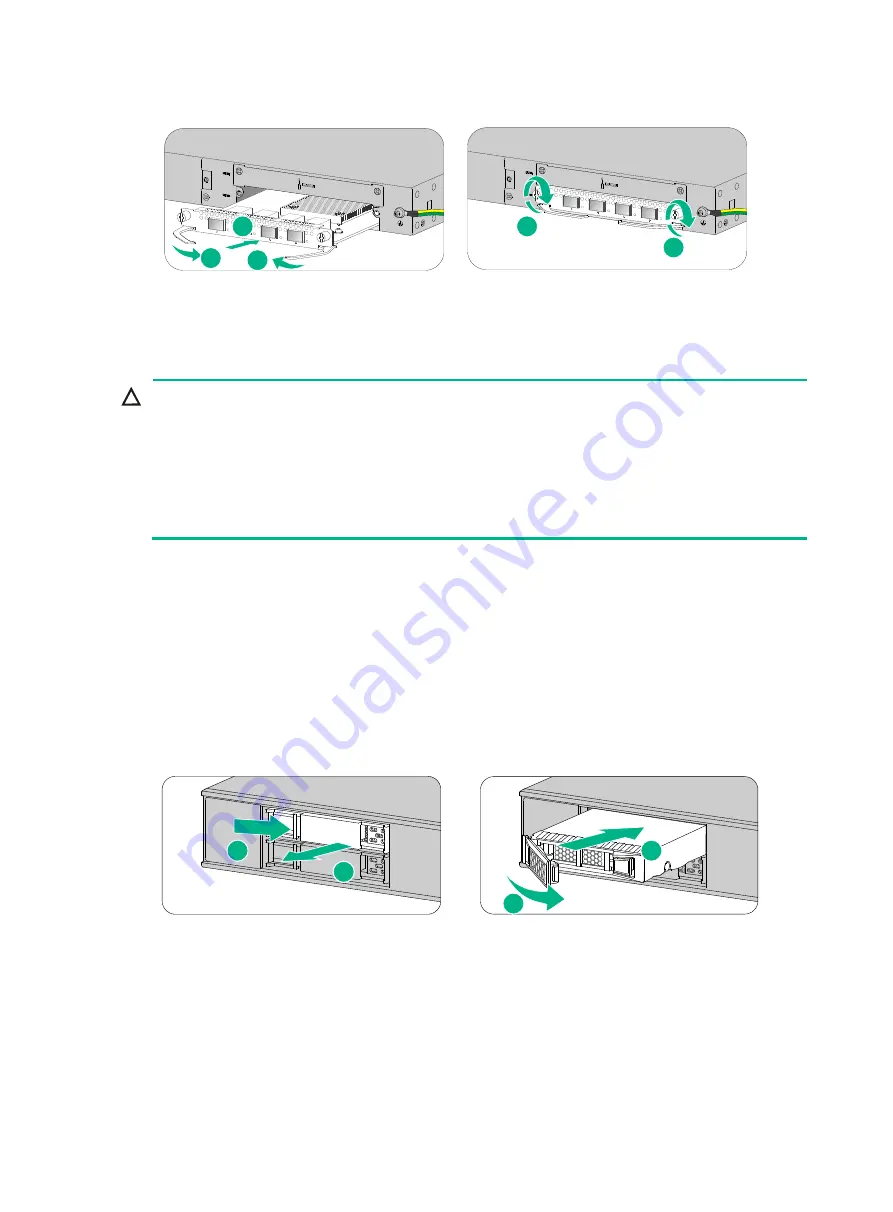
Figure2-18 Installing an interface module 


Installing a drive 


CAUTION: 

  Do not hot swap drives. 

  To avoid damage to drives, always hold a drive by its sides. Do not touch any components and do 

not squeeze, vibrate, or strike a drive. 

  Install a filler panel in empty drive slots to prevent dust and ESD damage. 

  Before using a drive, execute the 

fdisk

 and 

format

 commands from the CLI to partition and 

format the drive. 


The  device  does not come with any drives and cannot recognize drives from other vendors. 
Purchase drives from H3C as needed. 

To install a drive: 

1. 

Wear an ESD wrist strap and make sure it makes good skin contact and is reliably grounded. 

2. 

Remove the filler panel from the drive slot. 

3. 

Press the button on the drive panel to release the locking lever. 

4. 

Hold the locking lever and push the drive into the slot slowly along the guide rails. Then close 
the locking lever. 

Figure2-19 Installing a drive 


Connecting Ethernet cables 

Connecting a copper Ethernet port 

You can use either a straight-through or a cross-over network cable. For more information  about 
Ethernet twisted pair cables, see "Ethernet twisted pair cable." 

1

2

2

3

3

2

1

3

4

Summary of Contents for SecPath F1070

Page 1: ...Installing power modules 16 Installing a power module for an F1070 or F1080 firewall 16 Installing a power module for an F1090 firewall 17 Installing an interface module 18 Installing a drive 19 Conn...

Page 2: ...em 6 41 Password loss 6 41 Cooling system failure 6 42 Software loading failure 6 42 7 Appendix A Chassis views and technical specifications 7 43 Chassis views 7 43 F1005 F1010 7 43 F1020 7 43 F1030 F...

Page 3: ...iii RJ 45 to DB9 console cable 9 60 Micro USB console cable 9 60 Ethernet twisted pair cable 9 61 Introduction 9 61 Making an Ethernet twisted pair cable 9 64 Optical fiber 9 64...

Page 4: ...nderstood or followed can result in data loss data corruption or damage to hardware or software General safety recommendations Do not place the firewall on an unstable case or desk The firewall might...

Page 5: ...emit invisible laser light Do not stare into beams or view directly with optical instruments when the firewall is operating The firewall is a Class 1 laser device Before you disconnect the fiber conn...

Page 6: ...in the equipment room Lasting high relative humidity can cause poor insulation electricity leakage mechanical property change of materials and metal corrosion Lasting low relative humidity can cause...

Page 7: ...the air inlet and outlet vents of the chassis 19 inch rack mounting Ensure a minimum clearance of 80 mm 3 15 in around the air inlet and outlet vents of the chassis and a distance of 1U 44 45 mm or 1...

Page 8: ...es only indoors If part of the network cable of an Ethernet port must be routed outdoors connect a lightning arrester to the cable before you plug the cable into the port Lightning protection To prote...

Page 9: ...ied for other models Rubber feet Power cord retainer clip Power cord Grounding cable Console cable Pre installation checklist Table1 4 Checklist before installation Item Requirements Result Installati...

Page 10: ...grid system Separate the protection ground of the firewall from the grounding device or lightning protection grounding device as far as possible Keep the firewall far away from radio stations radar a...

Page 11: ...8 Item Requirements Result accessories User supplied tools Reference Documents shipped with the firewall Online documents...

Page 12: ...ll and rack are reliably grounded and you wear an ESD wrist strap 5 Installing power modules Before you install a power module make sure the power module is not connected to any power source and the g...

Page 13: ...ard 19 inch rack WARNING To avoid bodily injury and device damage use a minimum of two persons to rack mount the firewall CAUTION For adequate heat dissipation ensure a minimum clearance of 80 mm 3 15...

Page 14: ...ith the firewall Figure2 3 Attaching mounting brackets and shoulder screws to the firewall 6 Attach the rear mounting brackets to the rear rack posts The rear mounting brackets can be attached to the...

Page 15: ...ing brackets with the wide flange inside the rack Figure2 5 Attaching the rear mounting brackets with the wide flange outside the rack 7 Mount the firewall in the rack Use M6 screws to secure the moun...

Page 16: ...firewall by using front mounting brackets The F1005 and F1010 firewalls support this installation method To install the firewall in a standard 19 inch rack by using front mounting brackets 1 Wear an E...

Page 17: ...ing brackets to both sides of the firewall with M4 screws provided with the firewall Figure2 9 Attaching the front mounting brackets to the firewall 6 Mount the firewall in the rack Use M6 screws to s...

Page 18: ...all with a grounding strip If a grounding strip is available at the installation site connect the grounding cable through the grounding strip To connect the grounding cable 1 Remove the grounding scre...

Page 19: ...f the grounding cable Attach the hook to the grounding point and secure the hook with the screw Figure2 12 Grounding the firewall with the grounding terminal on the rack Installing power modules CAUTI...

Page 20: ...er module slowly into the slot along the guide rails 3 Use a Phillips screwdriver to fasten the captive screws on the power module to secure the power module in place Figure2 14 Installing a power mod...

Page 21: ...ejector levers of the interface module while inserting it into an upper slot The F1005 and F1010 do not support interface modules No interface modules are provided with the firewall Purchase them as n...

Page 22: ...e drives from other vendors Purchase drives from H3C as needed To install a drive 1 Wear an ESD wrist strap and make sure it makes good skin contact and is reliably grounded 2 Remove the filler panel...

Page 23: ...nd clean Make sure the fiber connector matches the transceiver module Before connecting a fiber make sure the optical power at the receiving end does not exceed the transceiver module s upper threshol...

Page 24: ...iber connector 4 Identify the Rx and Tx ports on the transceiver module Plug one end of the optical fiber into the transceiver module in the firewall and plug the other end into the transceiver module...

Page 25: ...the power receptacle 4 Connect the other end of the power cord to an AC power source Figure2 23 Connecting an AC power cord for an F1005 or F1010 firewall Connecting an AC power cord for an F1020 F103...

Page 26: ...ord 2 Connect the other end of the power cord to an AC power source Figure2 26 Connecting an AC power cord using a power cord retainer clip to secure the power cord Figure2 27 Connecting an AC power c...

Page 27: ...rd connector with a flathead screwdriver to secure the power cord connector 3 Use a cable tie to secure the power cord to the handle 4 Connect the other end of the power cord to a DC power source Figu...

Page 28: ...ipation around the firewall The firewall and its components are installed securely The screws are fastened tightly The power source specifications are as required by the firewall The grounding cable a...

Page 29: ...SB console port The interface modules if any are installed correctly Starting the firewall and observing the initial startup conditions 1 Turn on the circuit breakers to power on the firewall 2 Observ...

Page 30: ...Known answer test for HMAC SHA224 passed Known answer test for HMAC SHA256 passed Known answer test for HMAC SHA384 passed Known answer test for HMAC SHA512 passed Known answer test for AES passed Kno...

Page 31: ...ogging in from the Web interface Logging in from the serial console port or micro USB console port Logging in through Telnet Logging in from the Web interface The default Web interface login informati...

Page 32: ...t or micro USB console port you must run a terminal emulator program TeraTermPro or PuTTY on your configuration terminal and configure the following settings for the terminal For more information abou...

Page 33: ...replace a power module for an F1070 or F1080 firewall 1 Face the rear panel of the firewall 2 Use a Phillips screwdriver to loosen the captive screw of the power module 3 Hold the power module with on...

Page 34: ...e an interface module To install two or more interface modules use the upper interface module slots as a best practice If you have installed an interface module in a lower slot you must press down the...

Page 35: ...side of the drive panel to release the locking lever 4 Hold the locking lever and pull the drive out of the slot 5 Install a new drive For the installation procedure see Installing a drive Figure4 4...

Page 36: ...tall dust caps to the LC connectors 3 Pivot the clasp of the transceiver module down to the horizontal position and gently pull the transceiver module out Figure4 6 Removing the transceiver module 4 I...

Page 37: ...FCard Num 0 Displaying the software and hardware version information for the firewall Use the display version command to display software and hardware version information for the firewall Sysname disp...

Page 38: ...NUFACTURING_DATE 2016 04 29 VENDOR_NAME H3C Fan 0 The operation is not supported on the specified fan Fan 1 The operation is not supported on the specified fan Fan 2 The operation is not supported on...

Page 39: ...t memory is measured in KB Slot 1 Total Used Free Shared Buffers Cached FreeRatio Mem 1718140 921604 796536 0 1108 187644 46 4 Buffers Cache 732852 985288 Swap 0 0 0 Table5 3 Output description Field...

Page 40: ...rature information of the firewall IMPORTANT Only F1020 F1030 F1050 F1060 F1070 F1080 and F1090 firewalls support the display environment command Use the display environment command to display the tem...

Page 41: ...ave or display diagnostic information Y save N display Y N y Please input the file name gz flash diag gz Diagnostic information is outputting to flash diag gz Please wait Save successfully To view the...

Page 42: ...firewall prompts REBOOT IN ONE MINUTE and reboots in one minute If you are performing file operations when the firewall is to be rebooted the system does not execute the reboot command for security T...

Page 43: ...5 40 Task Command Remarks and specify a reboot waiting time scheduler reboot delay...

Page 44: ...ssue 1 Verify that the power supply system is operating correctly 2 Verify that the serial console cable or micro USB console cable is correctly connected 3 Verify that the serial console cable or mic...

Page 45: ...formation about the firewall temperature in the display environment command output varies by firewall model Only F1020 F1030 F1050 F1060 F1070 F1080 and F1090 firewalls support the display environment...

Page 46: ...ne console port One drive slot Figure7 1 Front panel 1 Drive slot 2 Console port 3 USB ports host mode Type A connector 4 Combo interfaces 5 Bypass ports 6 10 100 1000BASE T copper ports 7 LEDs 8 Mana...

Page 47: ...receptacle 2 Interface module slot 1 3 Interface module slot 2 not supported 4 Grounding screw F1030 F1050 F1060 The F1030 F1050 or F1060 firewall provides the following ports on the front panel Sixt...

Page 48: ...BASE T autosensing Ethernet copper ports Eight 1000BASE X fiber ports Two 10GBASE R fiber ports Two USB ports One console port Two drive slots Figure7 7 Front panel 1 Drive slots 2 LEDs 3 10 100 1000B...

Page 49: ...Management Ethernet port 1 MGMT 3 10 100 1000BASE T copper ports 4 10GBASE R fiber ports 5 1000BASE X fiber ports 6 LEDs 7 Reset button 8 Micro USB port 9 USB port host mode Type A connector 10 Conso...

Page 50: ...00 1000BASE T Ethernet copper ports When the firewall is operating correctly the four ports operate as common data ports When the firewall is powered off the four ports are divided into two bypass por...

Page 51: ...yption modules The appearance of network data encryption modules varies by models For more information see H3C SecPath Firewall Network Data Encryption Module Guide Table7 2 describes the hardware and...

Page 52: ...1090 NS SSD 480G SATA SFF Yes Yes Yes Yes NS HDD 500G SATA SFF No Yes No Yes NS HDD 1T SATA SFF No Yes No Yes Power modules The F1070 F1080 F1090 firewall comes with power module slot PWR0 installed w...

Page 53: ...SR450 12AHD PSR450 12D AC power modules PSR150 A1 The PSR150 A1 power module with a product code of PSR150 A1 B provides a maximum output power of 150 W Figure7 14 PSR150 A1 power module 1 Handle 2 Po...

Page 54: ...es PSR150 D1 The PSR150 D1 power module with a product code of PSR150 D1 B provides a maximum output power of 150 W Figure7 16 PSR150 D1 power module 1 Handle 2 Power receptacle PSR450 12D The PSR450...

Page 55: ...modules CAUTION You can install high voltage DC power modules only on the F1090 firewall PSR450 12AHD The PSR450 12AHD power module with a product code of PSR450 12AHD provides a maximum output power...

Page 56: ...H W D Weight NSQM1GT4PFC 19 150 172 9 mm 0 75 5 91 6 81 in 0 45 kg 0 99 lb NSQM1GP4FBA 19 150 172 9 mm 0 75 5 91 6 81 in 0 42 kg 0 93 lb NS NIM TG6A 19 150 172 9 mm 0 75 5 91 6 81 in 0 4 kg 0 88 lb N...

Page 57: ...GB NS HDD 500G SATA SFF 500 GB NS HDD 1T SATA SFF 1 TB Power consumption The system power consumption includes the power consumptions of the chassis and the removable components Chassis Table7 11 Chas...

Page 58: ...ications Model Rated input voltage range Maximum input current Maximum power PSR150 A1 100 VAC to 240 VAC 50 Hz or 60 Hz 2 A 150 W PSR250 12A1 100 VAC to 240 VAC 50 Hz or 60 Hz 5 A 250 W Table7 16 DC...

Page 59: ...port specifications Item Specification Connector Micro USB Standard compliant Micro USB Baud rate 9600 bps default to 115200 bps Cable type USB console cable Transmission distance 10 m 32 81 ft Servi...

Page 60: ...e specifications Transceiver module Central wavelength Connector Fiber Max transmission distance SFP GE SX MM850 A 850 nm LC 50 125 m multi mode optical fiber 0 55 km 1804 46 ft SFP GE LX SM1310 A 131...

Page 61: ...69 03 ft 66 m 216 54 ft 62 5 125 m multi mode optical fiber 33 m 108 27 ft 26 m 85 30 ft SFP XG LX220 MM131 0 1310 nm LC 62 5 125 m multi mode optical fiber 220 m 721 78 ft 50 125 m multi mode optical...

Page 62: ...orrectly 10 100 1000BASE T copper port LED 10 100 100 0BASE T Off No link is present Steady green A link is present Flashing green The port is receiving and sending data 1000BASE X fiber port LED 1000...

Page 63: ...on the firewall Figure9 1 RJ 45 to DB9 console cable Table9 1 RJ 45 to DB9 console cable pinouts RJ 45 Signal Direction DB 9 1 RTS 7 2 DTR 4 3 TXD 3 4 CD 1 5 GND 5 6 RXD 2 7 DSR 6 8 CTS 8 Micro USB c...

Page 64: ...twisted pair cables can be classified into category 3 category 4 category 5 category 5e category 6 and category 7 cables based on performance In LANs category 5 category 5e and category 6 are commonl...

Page 65: ...pin 3 white green stripe pin 4 blue solid pin 5 white blue stripe pin 6 green solid pin 7 white brown stripe pin 8 brown solid Ethernet twisted pair cables can be classified into straight through and...

Page 66: ...5 Reserved N A BIDC Bi directional data cable C 6 Rx Receives data BIDB Bi directional data cable B 7 Reserved N A BIDD Bi directional data cable D 8 Reserved N A BIDD Bi directional data cable D Tab...

Page 67: ...an appropriate length of the cable sheath The length is typically that of the RJ 45 connector 3 Untwist the pairs so that they can lay flat and arrange the colored wires based on the wiring specificat...

Page 68: ...llow these guidelines when you connect an optical fiber Before connecting an optical fiber make sure the connector and cable type match the interface module The fiber Ethernet port of the firewall sup...

Reviews: