


Installation Manual
H3C SecPath F1000-E Firewall
Chapter 1 Product Overview
1-13
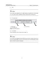
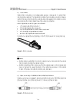
DB-25 (female) connector, either of which can be plugged into the serial interface of the
Console terminal as needed.
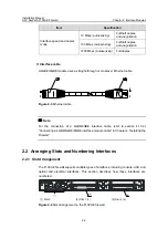
Figure 1-7
AUX cable
Table 1-12
AUX cable pinouts
Pin (RJ-45)
Signal direction
Pin (DB-9)
Signal
1
Æ
7 RTS
2
Æ
4 DTR
3
Æ
3 TXD
4
Å
1 DCD
5 — 5 GND
6
Å
2 RXD
7
Å
6 DSR
8
Å
8 CTS
Note:
For the connection of the AUX cable, refer to section 4.10.2 “Connecting the AUX Port
to a Modem” in Chapter 4 “Installing the Firewall”.
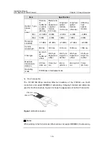
III. GE combo interfaces
1) Introduction
The F1000-E provides four fixed GE combo interfaces. Each GE combo interface
consists of an electrical Ethernet interface and an optical Ethernet interface, but either
the electrical Ethernet interface or the optical Ethernet interface can operate at one
time.
z
For the rate and negotiation mode when the electrical Ethernet interface is
operating, see Table 1-13.


