


22
POS interface configuration examples
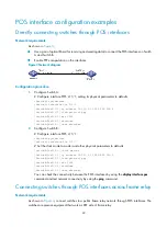
Directly connecting switches through POS interfaces
Network requirements
As shown in
,
•
Use a pair of optical fibers (for receiving and sending data) to connect the POS interfaces on Switch
A and Switch B.
•
Enable PPP encapsulation on the interfaces.
Figure 3
Network diagram
Configuration procedure
1.
Configure Switch A:
# Configure interface POS 2/1/1, setting its physical parameters to defaults.
<SwitchA> system-view
[SwitchA] interface Pos 2/1/1
[SwitchA-Pos2/1/1] ip address 10.110.1.10 255.255.255.0
[SwitchA-Pos2/1/1] link-protocol ppp
[SwitchA-Pos2/1/1] mtu 1500
[SwitchA-Pos2/1/1] shutdown
[SwitchA-Pos2/1/1] undo shutdown
2.
Configure Switch B:
# Configure interface POS 2/1/1.
<SwitchB> system-view
[SwitchB] interface Pos 2/1/1
# Set the clock mode to master and other physical parameters to defaults.
[SwitchB-Pos2/1/1] clock master
[SwitchB-Pos2/1/1] ip address 10.110.1.11 255.255.255.0
[SwitchB-Pos2/1/1] link-protocol ppp
[SwitchB-Pos2/1/1] mtu 1500
[SwitchB-Pos2/1/1] shutdown
[SwitchB-Pos2/1/1] undo shutdown
You can check the connectivity between the POS interfaces by using the
display interface pos
command and test network connectivity by using the
ping
command.
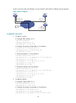
Connecting switches through POS interfaces across frame relay
Network requirements
As shown in
, connect switches to a public frame relay network through POS interfaces. The
switches are premise equipment that work as DTE side of frame relay.


