


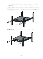


2-19
The S6826-48Y8C and S9826-32C switches each have two power supply slots and come with
power supply slot PWR1 empty and PWR2 installed with a filler panel. You can install power supplies
for the switch as required.
For information about the available power supplies, see
S6826 & S9826 Switch Series Hardware
Information and Specifications.
Figure2-29 Installation procedure
Figure2-30 Removal procedure
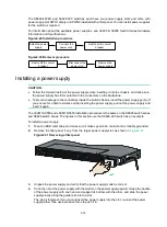
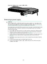
Installing a power supply
CAUTION:
•
Follow the forward inertia of the power supply when inserting it into the chassis, and make sure
the power supply has firm contact with the connectors on the backplane.
•
To prevent damage to the connectors inside the switch chassis, insert the power supply gently. If
you encounter a hard resistance while inserting the power supply, pull out the power supply and
insert it again.
The LSVM1AC650 and LSVM1DC650 installation procedure is the same on the S6826 switch series
and S9826 switch series. The figures in this section use the S9826-32C switch as an example.
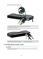
To install a power supply:
1.
Wear an ESD wrist strap and make sure it makes good skin contact and is reliably grounded.
2.
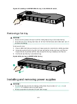
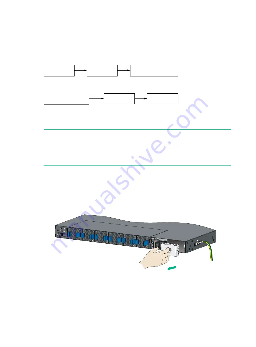
Remove the filler panel, if any, from the target power supply slot, as shown in
Figure2-31 Removing a filler panel
3.
Unpack the power supply and verify that the power supply model is correct.
4.
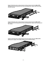
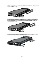
Correctly orient the power supply with the words on the power supply upward. Grasp the handle
of the power supply with one hand and support its bottom with the other, and slide the power
supply slowly along the guide rails into the slot.
The slot is foolproof. If you cannot insert the power supply into the slot, re-orient the power
supply rather than use excessive force to push it in.
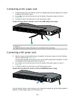
Install the power
supply
Connect the
power cord
Switch on the circuit
breaker
Disconnect the
power cord
Remove the
power supply
Switch off the circuit
breaker


