


5-1
5
Cooling system
CAUTION:
The chassis and power supplies use separate air aisles. Make sure the two aisles are not blocked
when the switch is operating.
To dissipate heat timely and ensure system stability, the switch uses the front-rear air aisle cooling
system. Consider the site ventilation design when you plan the installation site for the switch.
Table5-1 Cooling system for the switch
Switch model
Available fan trays
Airflow direction
•
S9826-32C
•
S6826-48Y8
C
LSWM1FANSA
From the power supply side to the port side
LSWM1FANSAB
From the port side to the power supply side
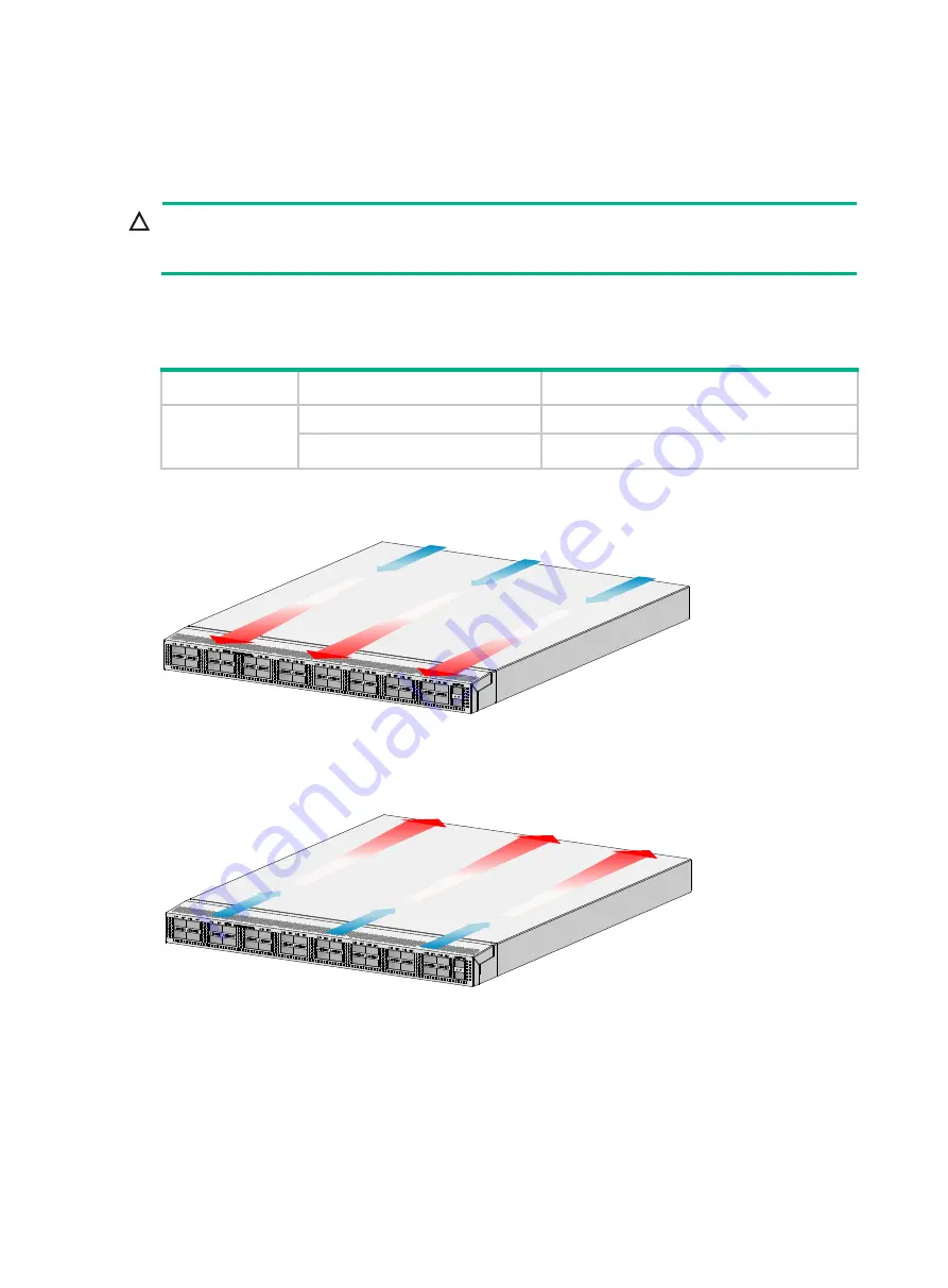
Figure5-1 Airflow from the power supply side to the port side through the S9826-32C chassis
(with LSWM1FANSA fan trays)
Figure5-2 Airflow from the port side to the power supply side through the S9826-32C chassis
(with LSWM1FANSAB fan trays)


