background image


2-20 

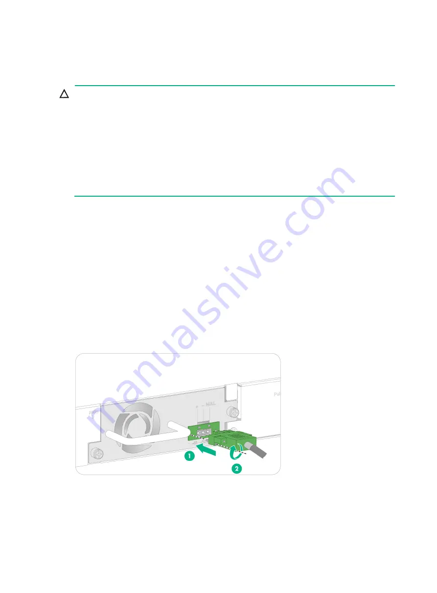
Connecting the power cord for a PSR150-D1 or PSR560-56D 
power supply 


CAUTION: 

  Connect the other ends of the wires for a PSR150-D1 power supply to a –48 VDC power source, 

with the negative wire (

 or 

L–

) to the negative terminal (

) and the positive wire (

+

 or 

M/N

) to the 

positive terminal (

+

). 

  To use a –48 VDC power source to supply power to the power supply, use the DC power cord 

supplied with the power supply. 

  To use an H3C RPS (–54 VDC) to supply power to the power supply, use a compatible RPS 

power cord to connect the RPS to the power supply. 

  The power cord color code scheme i

Figure2-29

 is for illustration only. The cable delivered for 

your country or region might use a different color scheme. When you connect the power cord, 
always identify the polarity symbol on its wires. 


The power cord connection procedure is the same for the PSR150-D1 and PSR560-56D power 
supplies. The following procedure uses a PSR150-D1 power supply as an example. 

To connect the power cord for a PSR150-D1 power supply: 

1. 

Wear an ESD wrist strap and make sure it makes good skin contact and is reliably grounded. 

2. 

Unpack the power cord, correctly orient the plug at one end of the cable with the power 
receptacle on the power supply, and insert the plug into the power receptacle (see callout 1 in 

Figure2-29

). 

The power receptacle is foolproof. If you cannot insert the plug into the receptacle, re-orient the 
plug rather than use excessive force to push it in. 

3. 

Tighten the screws on the plug with a flat-blade screwdriver to secure the plug in the power 
receptacle (see callout 2 in 

Figure2-29

). 

4. 

Connect the two wires at the other end of the power cord to a –48 VDC power source or an 
RPS. 

Figure2-29 Connecting the power cord for a PSR150-D1 power supply 


Summary of Contents for S5170-EI Series

Page 1: ...SR560 56D PSR720 56A or PSR1110 56A power supply 2 15 Removing a PSR180 56A PSR360 56A PSR560 56D PSR720 56A or PSR1110 56A power supply 2 16 Connecting the power cord 2 17 Connecting the power cord f...

Page 2: ...and troubleshooting 5 1 Power supply failure 5 1 Built in power supply failure 5 1 Removable power supply failure 5 1 Fan tray failure 5 2 Configuration terminal display issues 5 2 No display 5 2 Gar...

Page 3: ...8S EI LS 5570S 28S EI LS 5570S 28S EI GL S5570S 54S EI LS 5570S 54S EI LS 5570S 54S EI GL S5570S 28S HPWR EI LS 5570S 28S HPWR EI S5570S 54S PWR EI LS 5570S 54S PWR EI S5570S 36F EI LS 5570S 36F EI LS...

Page 4: ...e requirements listed in Table1 2 Table1 2 Checking list for the installation environment Item Requirements Ventilation and heat dissipation CAUTION To ensure correct operation of your device make sur...

Page 5: ...esponding network interface Keep the signal cables far from power cords and lightning rod down conductors As a best practice route power cords indoors If an AC power cord is routed from outdoors conne...

Page 6: ...y from pollution sources Do not smoke eat or drink in the equipment room Use double layer glass in windows and seal doors and windows with dust proof rubber strips Use screen doors and window screens...

Page 7: ...site meets the installation requirements The switch can operate correctly in an A1 or A2 installation site Availability issues might occur if you install the switch in an A3 B1 B2 or C installation s...

Page 8: ...ower distribution or power supply environment Table1 7 Requirements for power distribution or power supply environment Item Requirements Preparation The power supply must be available before you insta...

Page 9: ...8 Installation accessories Code Description Quantity Applicable device models N A Front mounting kit including a pair of front mounting brackets and eight M4 screws 1 pair provided All models N A Rea...

Page 10: ...standard AC power cord in China 1 provided for the switch with a built in power supply 1 provided with removable power supplies All models N A DC power cord 1 provided with DC power supplies S5570S EI...

Page 11: ...ission Otherwise H3C shall not be liable for any consequence Figure2 1 Hardware installation flow Start Install the switch Ground the switch Connect the power cords Verify the installation Turn on cir...

Page 12: ...30MS U PWR EI Using front and rear mounting brackets Select an installation position for the front mounting brackets as required near the power supply side or port side Install the rear mounting brack...

Page 13: ...the other mounting position near the power supplies for the front mounting brackets Select one position as needed To attach the front mounting brackets to the chassis 1 Place the wide flange of the mo...

Page 14: ...at the front mounting brackets have been securely attached to the switch chassis See Attaching the front mounting brackets to the switch 3 Attach cage nuts to the front rack posts 4 One person support...

Page 15: ...re2 6 Mounting the switch in the rack port side mounting position for the front mounting brackets Figure2 7 Mounting the switch in the rack power supply side mounting position for the front mounting b...

Page 16: ...h the mounting bracket to the chassis As a best practice use a torque of 12 kgf cm 1 18 Nm to fasten the M4 screws 4 Repeat the preceding two steps to attach the other mounting bracket to the chassis...

Page 17: ...with the wide flange inside the rack Figure2 10 Attaching the rear mounting brackets to the rack with the wide flange outside the rack Mounting the switch in the rack 1 Wear an ESD wrist strap Make s...

Page 18: ...he other and pushes the chassis into the rack gently Make sure the shoulder screws rest firmly on the upper edge of the rear mounting brackets See Figure2 11 and Figure2 12 5 The other person attaches...

Page 19: ...s bottom with dry cloth 3 Attach the rubber feet to the four round holes in the chassis bottom 4 Place the switch with upside up on the workbench Grounding the switch WARNING Correctly connecting the...

Page 20: ...t the switch to a grounding strip in the equipment room If a grounding strip is available at the installation site use the grounding cable provided with the switch to connect the switch to the groundi...

Page 21: ...grounding conductor buried in the earth ground If the installation site does not have grounding strips but earth ground is available hammer a 0 5 m 1 64 ft or longer angle iron or steel tube into the...

Page 22: ...power supply slots You can install one or two power supplies for the switch as required For the power supplies available for the switch and their specifications see S5170 EI S5570S EI Switch Series H...

Page 23: ...ed 2 Remove the filler panel from the target power supply slot as follows a Remove the screws from the filler panel b Use a flathead screwdriver to remove the filler panel Figure2 18 Removing the fill...

Page 24: ...it makes good skin contact and is reliably grounded 2 Disconnect the power cord 3 Loosen the captive screws on the power supply with a Phillips screwdriver until they are completely disengaged 4 Gras...

Page 25: ...future use Figure2 21 Removing the filler panel from the target power supply slot 3 Unpack the power supply Make sure the power supply model is as required Keep the packaging box and packaging bag fo...

Page 26: ...6A and PSR1110 56A power supplies The following procedure uses the PSR360 56A power supply as an example To remove a PSR360 56A power supply 1 Wear an ESD wrist strap and make sure it makes good skin...

Page 27: ...is off before installation Table2 3 Power cord connection procedures at a glance Power supply model Available power source Connection procedure reference Built in power supply AC power source Connecti...

Page 28: ...ect the other end of the power cord to an AC power source Figure2 25 Connecting the power cord for a built in power supply 1 Figure2 26 Connecting the power cord for a built in power supply 2 Connecti...

Page 29: ...2 27 3 Connect the female connector of the AC power cord supplied with the power supply to the power receptacle see callout 1 in Figure2 28 4 Pull the retainer clip rightwards to secure the connector...

Page 30: ...s wires The power cord connection procedure is the same for the PSR150 D1 and PSR560 56D power supplies The following procedure uses a PSR150 D1 power supply as an example To connect the power cord fo...

Page 31: ...60 56A PSR720 56A or PSR1110 56A power supply you can connect the power cord only to an AC power source For a PSR180 56A power supply you can connect the power cord to an AC or HVDC power source Figur...

Page 32: ...a configuration terminal Table3 1 Connection methods and console cables Connection method Console cable type Configuration terminal side connector Switch side connector Using the serial console port...

Page 33: ...h a crimped RJ 45 connector at one end for connecting to the serial console port of the switch and a DB 9 female connector at the other end for connecting to the serial port on the console terminal Fi...

Page 34: ...r on other operating systems see the installation guide in the driver compression package named by the corresponding operating system To connect the switch to the configuration terminal through a USB...

Page 35: ...m such as TeraTermPro on your configuration terminal You can use the emulator program to connect a network device a Telnet site or an SSH site For more information about the terminal emulator programs...

Page 36: ...h as software upgrade and file management The Boot ROM interface and menu options differ with software versions For more information about Boot ROM menu options see the software matching release notes...

Page 37: ...owchart Figure4 1 IRF fabric setup flowchart To set up an IRF fabric Step Description 1 Plan IRF fabric setup Plan the installation site and IRF fabric setup parameters Planning IRF fabric size and th...

Page 38: ...ng capacities of all member switches Plan the installation site depending on your network solution as follows Place all IRF member switches in one rack for centralized high density access Distribute t...

Page 39: ...m of one physical port to it When connecting two neighboring IRF member switches you must connect the physical ports of IRF port 1 on one switch to the physical ports of IRF port 2 on the other switch...

Page 40: ...ports can be forwarded in a queue with a higher priority S5170 36F EI S5170 36F EI DP S5570S 36F EI SFP and SFP ports on the front panel 10 100 1000BASE T autosensing Ethernet ports on the front panel...

Page 41: ...side If physical IRF ports are on different sides you must measure the distance between them to select an appropriate cable Connecting the IRF member switches in one rack Connect the IRF member switch...

Page 42: ...sic IRF settings For more information about configuring basic IRF settings see IRF configuration in the configuration guide for the switch Connecting the physical IRF ports Connect the IRF member swit...

Page 43: ...a reboot display irf configuration Display IRF fabric topology information display irf topology NOTE To avoid IP address collision and network problems configure a minimum of one multi active detecti...

Page 44: ...correctly 4 Verify that the operating temperature of the switch is in the acceptable range and the power supply has good ventilation Overtemperature can cause the power supply to stop working and ent...

Page 45: ...issue occurs contact H3C Support Configuration terminal display issues If the configuration environment setup is correct the configuration terminal displays booting information when the switch is pow...

Page 46: ...5 3 Data bits 8 Stop bits 1 Parity None Flow control None 2 If the issue persists contact H3C Support...

Reviews: