background image


3-12 

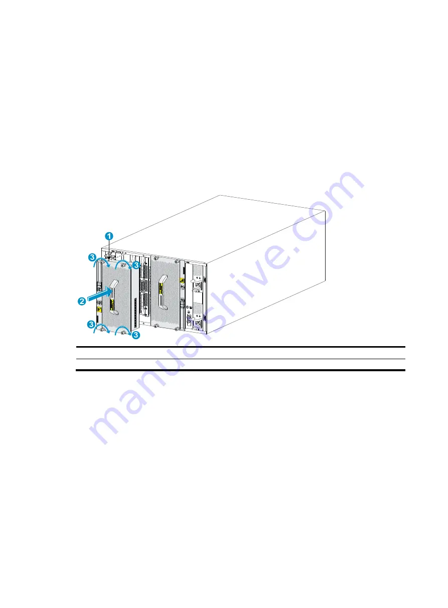
Installing fan trays for the S12504R 

1. 

Orient the fan tray correctly. 
To install a fan tray in the FAN1 slot, orient the fan tray so that the LEDs are on the left side of 

the front panel. To install a fan tray in the FAN2 slot, orient the fan tray so that the LEDs are on 

the right side of the front panel. 

2. 

As shown by callout 1 in 

Figure 3-10

, align the positioning pin on the fan tray with the 

positioning hole in the chassis. 

3. 

As shown by callout 2 in 

Figure 3-10

, hold the fan tray handle and insert the fan tray into the 

slot.   
Keep the fan tray as straight and stable as possible while inserting it into the slot. 

4. 

As shown by callout 3 in 

Figure 3-10

, fasten the captive screws on the fan tray. 

Figure 3-10 Installing a fan tray for the S12504R 


(1) Align the positioning pin on the fan tray with the positioning hole in the chassis 
(2) Insert the fan tray into the chassis 

(3) Fasten the captive screws on the fan tray 


Installing power modules 

The power module slots are located at the two sides of the rear panel.   
The installation procedure is the same for DC and AC power modules. 
To install a power module: 

1. 

Remove the filler panel, if any, from the target slot. As shown in 

Figure 3-11

put your 

forefinger in into the hole in the filler panel and pull out the filler panel along the guide rails. 

2. 

Correctly orient the power module. 
If you install the power module in a left power module slot, orient the power module with the 

latch above the handle. If you install the power module in a right power module slot, orient the 

power module with the latch below the handle. 

3. 

Holding the handle of the power module with one hand and supporting the bottom of the power 

module with the other, slide the power module along the guide rails into the slot until the latch 

locks the power module in place. 

Summary of Contents for S12500R Series

Page 1: ...H3C S12500R Ethernet Switch Router Series Installation Quick Start New H3C Technologies Co Ltd http www h3c com Document version 5PW101 20200426...

Page 2: ...espective owners Notice The information in this document is subject to change without notice All contents in this document including statements information and recommendations are believed to be accur...

Page 3: ...cable management brackets 3 5 Installing fabric modules 3 6 Installing a filler panel in a fabric module slot 3 8 Removing a filler panel from a fabric module slot 3 9 Installing fan trays 3 10 Insta...

Page 4: ...n ESD sign Examining the installation site The device must be used indoors To make sure the device operates correctly and to prolong its service lifetime the installation site must meet the load beari...

Page 5: ...1 2 Installation tools and equipment No installation tools and equipment are provided with the device Prepare them yourself as required...

Page 6: ...2 1 2 Installing the device Device dimensions Figure 2 1 S12516R dimensions 1 Fan tray handle 2 Mounting bracket 3 Cable management bracket...

Page 7: ...able management bracket Figure 2 3 S12504R dimensions with the LSXM104XFAN fan trays 1 Fan tray handle 2 Mounting bracket 3 Cable management bracket Figure 2 4 S12504R dimensions with the LSXM104XFANH...

Page 8: ...from the rear side of the mounting bracket front ear to the management bracket front end 875 mm 34 45 in from the rear side of the mounting bracket front ear to the fan tray handle at the rear of the...

Page 9: ...02 lb LSXM1BSR 630 mm 24 80 in to 900 mm 35 43 in 1 U LSTM2KSGD0 500 mm 19 69 in to 800 mm 31 50 in 2 U S12504R 120 kg 264 55 lb LSVM1BSR10 630 mm 24 80 in to 850 mm 33 46 in N A NOTE The LSXM1BSR sl...

Page 10: ...2 5 Figure 2 5 Installing cage nuts S12516R...

Page 11: ...2 6 Figure 2 6 Installing cage nuts S12508R Figure 2 7 Installing cage nuts S12504R 1U 2U 4U 2U 1U 2U...

Page 12: ...device damaging the device or even causing bodily injury To mount the device in the rack 1 Face the rear of the chassis towards the front of the rack 2 Place the device on the slide rails from the fr...

Page 13: ...t the grounding cable to a grounding strip 1 Unpack the grounding cable The grounding cable provided with the device is compliant with the NEBS standards The two hole grounding lug of the grounding ca...

Page 14: ...the grounding cable to a grounding strip S12516R 1 Use the grounding screws to attach the two hole grounding lug to the grounding point 2 Grounding sign 3 Grounding strip 4 Grounding post 5 Ring termi...

Page 15: ...amaging the connectors on the MPU To prevent a filler panel from being drawn into the chassis when fan speed is high use both hands to grasp the filler panel by its two sides during filler panel insta...

Page 16: ...Installing MPUs for the S12504R The S12504R MPU marks and MPU slot edges are pink marked To install an MPU for the S12504R 1 As shown by callout 1 in Figure 3 2 remove the filler panel from the targe...

Page 17: ...dules CAUTION To prevent a filler panel from being drawn into the chassis when the fan speed is high use both hands to grasp the filler panel by its two sides during filler panel installation and remo...

Page 18: ...ing on it upright Push the service module slowly and steadily into the slot along the guide rails Avoid touching other components in the chassis 3 As shown by callout 2 in Figure 3 3 pull the ejector...

Page 19: ...asten the captive screws on the service module Installing cable management brackets The cable management brackets are installed on the two sides of the service module slots As a best practice install...

Page 20: ...s Before installing a fan tray install fabric modules or filler panels in the fabric module slots the fan tray will cover To replace or install fabric modules in the slots covered by both fan trays wh...

Page 21: ...t it into the slot along the guide rails See callout 1 in Figure 3 6 Keep the module parallel to the slot to avoid touching other components in the chassis 4 As shown by callout 2 in Figure 3 6 contin...

Page 22: ...the filler panel with the side marked Up facing up Hold the filler panel front panel near the ejector levers with one hand and support its bottom with the other Place the filler panel bottom gently on...

Page 23: ...ller panel from a fabric module slot 1 As shown by callout 1 in Figure 3 8 loosen the captive screws on the ejector levers 2 As shown by callout 2 in Figure 3 8 rotate outward the ejector levers Then...

Page 24: ...aring an earmuff or earplug In addition make good preparation before the hot swapping to minimize the operation time IMPORTANT Fan trays cover fabric module slots Before you install a fan tray install...

Page 25: ...lot 2 Holding the upper fan tray handle with one hand and the lower fan tray handle with the other hand insert the fan tray into the slot Keep the fan tray as straight as possible To install a fan tra...

Page 26: ...with the positioning hole in the chassis 2 Insert the fan tray into the chassis 3 Fasten the captive screws on the fan tray Installing power modules The power module slots are located at the two side...

Page 27: ...breaker for it is turned off CAUTION Before powering on the device make sure the fan trays are installed correctly Connecting an AC power cord 1 Connect the AC power cord connector into the AC input...

Page 28: ...R Connecting a DC power cord 1 Connect the DC power cord connector to the DC input receptacle on the power module 2 Fasten the screw on the connector to secure the DC power cord in place 3 Connect the...

Page 29: ...emove the dust plug from the SFP SFP QSFP QSFP28 module if you are not to connect an optical fiber to the module Before you install an SFP SFP QSFP QSFP28 module remove the optical fiber if any from i...

Page 30: ...meter The cables are hot swappable Use SFP DAC cables to connect SFP ports QSFP DAC cables to connect QSFP ports QSFP28 DAC cables to connect QSFP28 ports and QSFP to SFP DAC cables to connect QSFP an...

Page 31: ...assis front edges on its two sides As a best practice route the cables from the left half of the chassis through the left cable management bracket and the cables from the right half of the chassis thr...

Page 32: ...female connector of the console cable to the serial port of the PC 2 Plug the RJ 45 connector of the console cable to the console port of the device Figure 5 1 Connecting a terminal to the console po...

Page 33: ...ting Normal Extended BootWare The Extended BootWare is self decompressing Done System image is starting Line aux0 is available Press ENTER to get started Press Enter at the prompt When the prompt Sysn...

Reviews: