background image


7-3 

Labels for devices 

A device label is used to identify the device name, model, address, installation date, and so on. 

Filling in labels 

You can print or write desired contents on labels. HP recommends that you print labels. 

To print labels, select a label printer and a label template as needed. For more information about 
using a label printer, see the user guide of the printer. 

To write labels, use black markers. A marker has two nibs. Be sure to use the smaller nib to write 
labels. 

Affixing labels 

After printing or writing a label, remove the label from the bottom page and affix it to the network 
cable, or the identification plate of the power cord. 

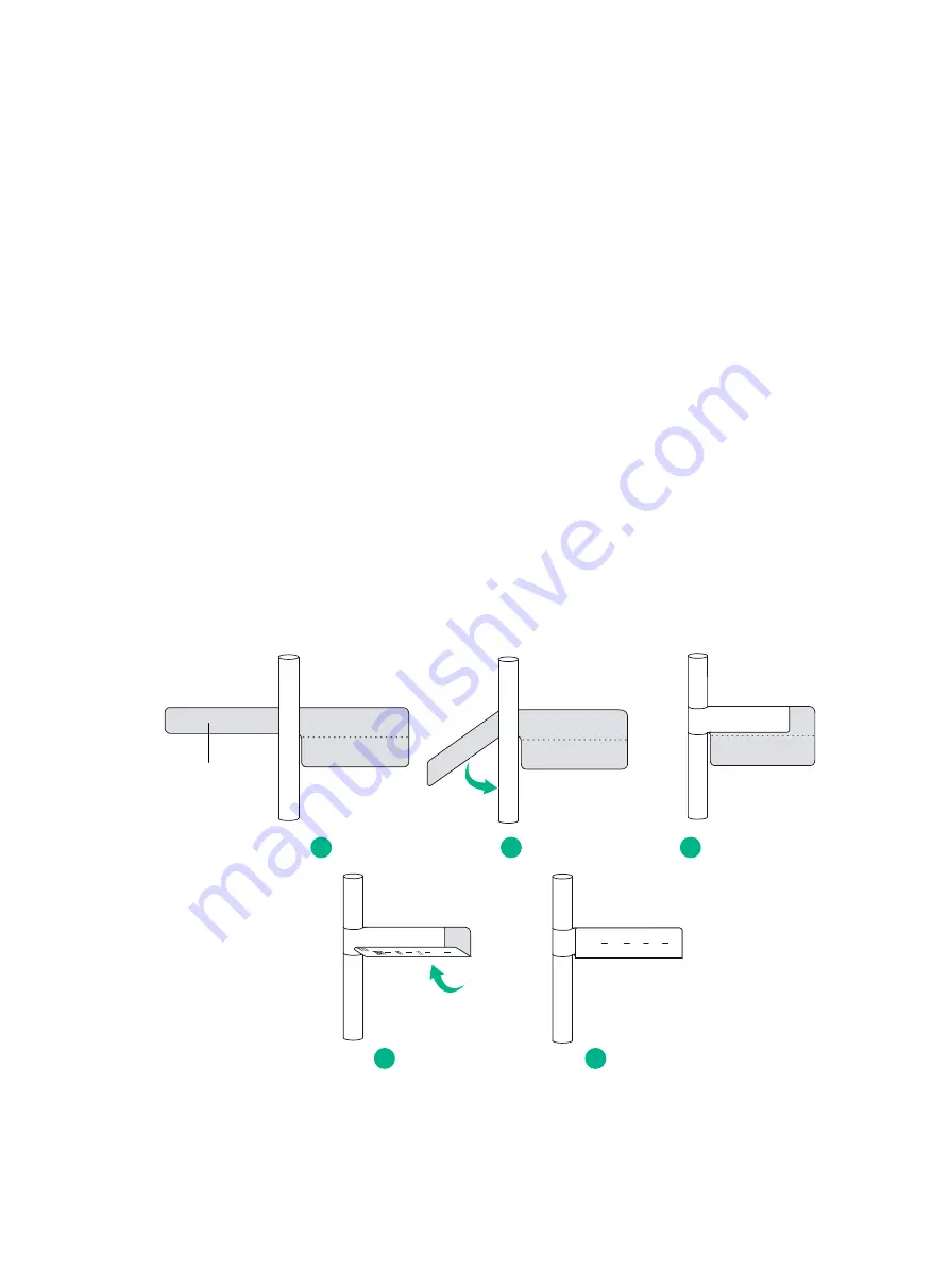
Affixing a label to a network cable 

Typically, a label is affixed 2 cm (0.79 in) away from the connector on a network cable. You can affix 
the label to other positions as needed. 

Figure 7-4

 shows how to affix a label when a cable is laid 

vertically. 

Figure 7-4 Affixing a label 


Figure 7-5

 shows the affixed labels when the cable is laid vertically and horizontally. 

Adhesive side

TO:

B02

03 12

1

2

3

4

5

Summary of Contents for S12500G-EF Series

Page 1: ...H3C S12500G EF Switch Series Installation Guide New H3C Technologies Co Ltd http www h3c com Document version 5W100 20221014...

Page 2: ...espective owners Notice The information in this document is subject to change without notice All contents in this document including statements information and recommendations are believed to be accur...

Page 3: ...ents arguments that you replace with actual values Square brackets enclose syntax choices keywords or arguments that are optional x y Braces enclose a set of required syntax choices separated by verti...

Page 4: ...s Convention Description Represents a generic network device such as a router switch or firewall Represents a routing capable device such as a router or Layer 3 switch Represents a generic switch such...

Page 5: ...ardware model configuration or software version It is normal that the port numbers sample output screenshots and other information in the examples differ from what you have on your device Documentatio...

Page 6: ...y recommendations 1 1 Electricity safety 1 1 Handling safety 1 1 ESD prevention 1 2 Laser safety 1 2 Examining the installation site 1 2 Weight support 1 2 Temperature 1 2 Humidity 1 3 Cleanliness 1 3...

Page 7: ...rds such as ungrounded power extension cables missing safety grounds and wet floors Locate the emergency power off switch in the room before installation so you can quickly shut power off when an elec...

Page 8: ...o ensure correct operation and long lifespan of your device the installation site must meet the requirements in this section Weight support Make sure the floor can support the total weight of the rack...

Page 9: ...nts In the worst case electrostatic adsorption can cause communication failure Table 1 3 Dust concentration limit in the equipment room Substance Concentration limit particles m 3 Dust particles 3 x 1...

Page 10: ...card type and density For more information about system power consumption calculation see H3C S12500G EF Switch Series Hardware Information and Specifications 2 Identify the number of power modules Th...

Page 11: ...requirements Reserve a minimum of 0 8 m 2 62 ft of clearance between the rack and walls or other devices Make sure the rack has enough space to accommodate the device For information about device dime...

Page 12: ...cription Quantity Applicable device models 2150A0HX S12516G EF mounting brackets 1 pair S12516G EF 2150A0J6 S12508G EF mounting brackets 1 pair S12508G EF 2113A35S S12516G EF MPU filler panel 1 S12516...

Page 13: ...odule filler panel S1251 6G E F 11 S1250 8G E F 5 All S12500G EF models 2112A0BQ S12500G EF power module slot adapter guide rail S1251 6G E F 12 S1250 8G E F 6 All S12500G EF models 2150A0J1 2150A0J0...

Page 14: ...ntity Applicable device models 26020141 26020075 M6 screw and cage nut S1251 6G E F 30 kits S1250 8G E F 14 kits All S12500G EF models 0404A1T8 Grounding cable 1 All S12500G EF models 28050001 ESD wri...

Page 15: ...ation preparations 2 1 Installing the device in a rack 2 2 Device dimensions and rack requirements 2 2 Attaching slide rails to the rack 2 4 Installing cage nuts for attaching mounting brackets 2 8 Mo...

Page 16: ...ck is sturdy and reliably grounded No obstruction inside or outside the rack interfere with installation of the chassis The heaviest device is placed at the bottom of the rack The rack can provide pow...

Page 17: ...2 2 Installing the device in a rack Device dimensions and rack requirements Figure 2 1 S12516G EF dimensions 1 Mounting bracket 2 Cable management bracket...

Page 18: ...r to the fan tray handle at the rear of the chassis A minimum of 800 mm 31 50 in in depth recommended A minimum of 115 mm 4 53 in between the front rack post and the front door A minimum of 675 mm 26...

Page 19: ...rails Model Adjustment range Occupied space S12516G EF S12508G EF LSXM1BSR 630 to 900 mm 24 80 to 35 43 in 1 RU LSTM2KSGD0 500 to 800 mm 19 69 to 31 50 in 2 RU LSTM1KSGD0 350 to 500 mm 13 78 to 19 69...

Page 20: ...he standard hole within the same RU A total of eight cage nuts are required with two cage nuts for each rack post 4 Align the installation holes on the front end of the slide rail with the cage nuts o...

Page 21: ...and LSTM1KSGD0 slide rails This section takes the LSTM2KSGD0 slide rails as an example To attach the LSTM2KSGD0 slide rails 1 Read the signs on the slide rails to identify the right and left slide rai...

Page 22: ...on the rack posts as shown by callout 2 in Figure 2 7 Each rack post requires six cage nuts a Insert the lower ear of a cage nut into the corresponding installation hole b Compress the upper and lowe...

Page 23: ...rack posts for attaching the mounting brackets 1 As shown in Figure 2 8 and Figure 2 9 mark the cage nut installation holes for the 12500G EF switch series 2 Install cage nuts into the marked square...

Page 24: ...he device to the rack If no mechanical lift is used cooperate with a minimum of four people to manually lift the device To rack mount the device 1 Orient the chassis with its rear facing towards the f...

Page 25: ...he correct holes Figure 2 10 Mounting the S12516G EF in the rack 1 Chassis handle 2 Slide the chassis into the rack 3 Use M6 screws to secure the mounting brackets to the rack Figure 2 11 Mounting the...

Page 26: ...unding lug of the grounding cable is used for connecting the chassis The ring terminal of the grounding cable is used for connecting the grounding strip 2 Remove the M6 grounding screw from the ground...

Page 27: ...516G EF 3 10 Installing a fabric module on the S12508G EF 3 12 Installing a filler panel in a fabric module slot 3 13 Removing a filler panel from a fabric module slot 3 14 Installing fan trays 3 15 I...

Page 28: ...d the air flow or take other protective measures Attaching an ESD wrist strap The device is provided with an ESD wrist strap To minimize ESD damage to electronic components wear the ESD wrist strap an...

Page 29: ...ot broken or blocked When you install an MPU avoid damaging the connectors on the MPU To prevent a filler panel from being drawn into the chassis when fan speed is high use both hands to grasp the fil...

Page 30: ...rs of the MPU outward when most part of the MPU is inserted in the slot 4 Push the MPU until the ejector levers make close contact with the slot edges 5 As shown by callout 3 in Figure 3 3 continue to...

Page 31: ...fy whether it is an MPU filler panel or service module filler panel As shown in Figure 3 4 an MPU filler panel does not have air vents but a service module filler panel has air vents on its front pane...

Page 32: ...ling cable management brackets Installing cable management brackets on the S12516G EF The S12516G EF came with two upper and two lower cable management brackets You install the upper and lower cable m...

Page 33: ...3 6 Figure 3 6 Cable management brackets Figure 3 7 Installing a cable management bracket...

Page 34: ...stallation position for the cable management bracket A cable management bracket has mark A 2 Align the captive screws on the cable management bracket with the holes in the mounting bracket 3 As shown...

Page 35: ...module slot install a filler panel in the slot To prevent card damage and ensure correct operation fabric modules can only be used with service modules of the same type Type P fabric modules have a ch...

Page 36: ...c module for an operating device first remove the fan tray that covers the slot of the fabric module Install the fan tray immediately after the replacement or installation After the fan tray starts op...

Page 37: ...hassis 3 As shown by callout 3 in Figure 3 13 release the ejector levers by pressing the spring clips when the fabric module is half way inserted into the slot 4 As shown by callout 4 in Figure 3 13 f...

Page 38: ...3 11 Figure 3 13 Installing a fabric module on the S12516G EF 1 Fabric module handle 2 Push the fabric module slowly into the slot...

Page 39: ...r lever with one hand and supporting the module bottom with the other place the module bottom on the bottom guide rails of the chassis Align the fabric module with the target slot and then insert it i...

Page 40: ...in place Installing a filler panel in a fabric module slot Install a filler panel in a fabric module slot if you are not to install a fabric module in it To install a filler panel in a fabric module...

Page 41: ...fabric module slot S12516G EF Removing a filler panel from a fabric module slot 1 As shown in Figure 3 17 loosen the captive screws on the filler panel 2 Pull the filler panel out of the slot Keep the...

Page 42: ...Let the fan blades completely stop before you remove the fan tray The fan tray is high and heavy To avoid device damage or bodily injury use two people to install or remove a fan tray CAUTION To avoid...

Page 43: ...screws IMPORTANT Captive screws are required to install a fan tray on the device As a best practice fasten a captive screw to a torque of 5 5 kgf cm 4 77 lbf in The device has three fan tray slots You...

Page 44: ...he others each installed with a filler panel Installing a PSR1600B 12A B power module 1 Remove the filler panel if any from the target slot As shown in Figure 3 19 put your forefinger in into the hole...

Page 45: ...21 use your thumb to press the power module slot adapter while squeezing the opening in the adapter with your fingers 3 As shown by callout 3 in Figure 3 21 pull the power module slot adapter part way...

Page 46: ...ule slot adapter part way out and then pull it rightwards to disengage the left tabs from the chassis 4 Pull the power module slot adapter out Figure 3 22 Installing a PSR2400 12AHAH B power module S1...

Page 47: ...ce Figure 3 23 Power switch S12516G EF 1 Power switch Connecting an AC power cord 1 Connect the AC power cord connector into the AC input receptacle of the power module 2 As shown in Figure 3 24 use a...

Page 48: ...the service modules in the QSFP28 ports if you are not to install transceiver modules or cables in the ports Installing an SFP QSFP QSFP28 module CAUTION Read the following instructions before you in...

Page 49: ...he module straight into the port For information about connecting an optical fiber see Connecting your device to the network Connecting an SFP QSFP QSFP28 QSFP to SFP copper cable CAUTION When you con...

Page 50: ...3 23 2 Plug the cable connector into the port Make sure the cable connector is correctly oriented...

Page 51: ...parameters 4 2 Powering on the device 4 2 Configuring the device 4 3 Configuring authentication on a user interface 4 3 Configuring the basic access function 4 3 Configuration example 4 4 Verifying t...

Page 52: ...upports a maximum of 32 concurrent VTY users Accessing the device for the first time The first time you access the device you must use a console cable to connect a console terminal for example a PC to...

Page 53: ...g on the device confirm the following information You know where the emergency power off device for the equipment room is located The device has been securely mounted All the cards have been correctly...

Page 54: ...erface to control access to the device Table 4 1 describes the Telnet login authentication methods available for a VTY user line Table 4 1 Telnet login authentication methods Authentication method Fea...

Page 55: ...role network admin Sysname line vty0 quit Configuring the basic network settings Configure IP addresses Create VLAN interface 1 Sysname interface vlan interface 1 Assign an IP address for example 192...

Page 56: ...y the IP configuration of Layer 3 interfaces display ip interface brief Display brief information about active routes in the routing table display ip routing table Display VLAN settings display vlan D...

Page 57: ...module 4 Examine the port LEDs for incorrect connection For more information about the LED status see H3C S12500G EF Switch Series Hardware Information and Specifications NOTE For the QSFP QSFP28 CXP...

Page 58: ...No display on the configuration terminal 5 1 Garbled display on the configuration terminal 5 2 System failures during operation 5 2 Power module failure 5 2 Fan tray failure 5 3 MPU failure 5 3 Servi...

Page 59: ...fications The MPUs and service modules provide port status LEDs with which you can detect port failures For more information about port status LEDs see H3C S12500G EF Switch Series Hardware Informatio...

Page 60: ...lated commands to locate the fault 2 If a configuration error is found re configure the device or restore the factory default settings For more information see H3C S12500G EF Switch Series Fundamental...

Page 61: ...to the same power source If the new power module can operate correctly the old power module has failed Contact your sales agent or local service engineer to replace the old power module 10 If the issu...

Page 62: ...he system software if it is not compatible with the service module 3 Calculate the total power consumption and make sure your power modules can provide enough power For more information see H3C S12500...

Page 63: ...erate correctly If the LEDs of the two interfaces are on the cable is in good condition Otherwise the cable is faulty Use a compliant cable to connect the interface For more information see H3C S12500...

Page 64: ...5 6 Brief explanation of the troubleshooting measures that have been taken...

Page 65: ...6 1 Replacing a module 6 3 Replacing an MPU or service module 6 3 Replacing a fabric module 6 4 Replacing a fan tray 6 5 Replacing a transceiver module 6 7 Replacing an SFP QSFP QSFP28 transceiver mod...

Page 66: ...device is operating Replacing a power module WARNING The power module might have a high temperature To avoid being burnt allow the power module to cool before touching them CAUTION Provide a circuit b...

Page 67: ...the release latch on the connector 2 Pull the connector out of the power module 5 Press the latch on the power module to the handle direction and pull the power module part way out of the slot 6 Hold...

Page 68: ...ule 2 Wear an ESD wrist strap and make sure it makes good skin contact and is reliably grounded For more information see Installing FRUs 3 Use a Phillips screwdriver to loosen the captive screws on th...

Page 69: ...e good preparation before hot swapping a fabric module to minimize the operation time To replace a fabric module 1 Prepare an antistatic mat to place the removed fabric module 2 Wear an ESD wrist stra...

Page 70: ...ury do not touch the spinning fans when you replace the fan tray When you hot swap a fan tray the fan rotation speed of the remaining fan trays automatically increases and the fan trays make louder no...

Page 71: ...makes good skin contact and is reliably grounded For more information see Installing FRUs 3 Lift the handle on the fan tray as shown by callout 1 in Figure 6 7 4 Loosen the captive screws on the fan...

Page 72: ...rials 6 Install a new SFP QSFP QSFP28 transceiver module in the port For the installation procedure see Installing FRUs If you are not to install a new SFP QSFP QSFP28 transceiver module in the port i...

Page 73: ...If you are not to install a new SFP QSFP QSFP28 QSFP to SFP copper cable in the port insert the dust plug that is provided with the service module into the port to prevent particles from entering the...

Page 74: ...ixing labels 7 3 Affixing a label to a network cable 7 3 Affixing a label to a power cord 7 4 Affixing a generic label 7 5 Affixing a label to a device 7 5 Guidelines 7 5 Examples 7 6 Engineering labe...

Page 75: ...fy the peer end of the cable on which the label is affixed As shown in Figure 7 1 write a network cable label as follows Write the position of the cable in Area 1 Write the position of the cable on th...

Page 76: ...ons It is applicable to all cables A mark TO is located at the upper left corner in the right area of the label to identify the peer end of the cable on which the label is affixed The meaning of the d...

Page 77: ...two nibs Be sure to use the smaller nib to write labels Affixing labels After printing or writing a label remove the label from the bottom page and affix it to the network cable or the identification...

Page 78: ...s bundled 2 cm 0 79 in away from the connector You can affix the label to other positions as needed Figure 7 6 shows how to affix a label when a cable is laid horizontally Figure 7 6 Affixing a label...

Page 79: ...able For the example of affixed labels see Figure 7 8 Figure 7 8 Affixing a generic label Affixing a label to a device Remove the device label and stick it to the device You can stick a device label t...

Page 80: ...p down and left right order with two digits for example 01 MN Z MN Rack number M Row number of the rack in the equipment room in the range of A to Z N Column number of the rack in the equipment room i...

Page 81: ...hat connects two devices Table 7 2 Information on labels affixed to the fiber between two devices Content Meaning Example MN B C D R T MN Rack number M Row number of the rack in the equipment room in...

Page 82: ...column number of ODF M Row number of the rack in the equipment room in the range of A to Z N Column number of the rack in the equipment room in the range of 01 to 99 For example G01 is the ODF of Row...

Page 83: ...inet and distribution box BC identifies the row and column number of the 48V connector if there is no row number or column number or the connector can be identified without them BC can be omitted RTN...

Page 84: ...d related PGND and RTN cables are covered with insulating sheath so the labels only need to contain AC and the cabinet number The labels for AC power cords are affixed to one side of the identificatio...

Page 85: ...or devices These labels can be affixed to any device You can fill in the device name model IP address serial number installation address and installation date on a device label Figure 7 14 Example of...

Page 86: ...i Contents 8 Appendix B Cabling recommendations 8 1 Routing cables 8 1 Routing power cords 8 1 General cabling requirements 8 1 Prerequisites 8 2 Cable management guidelines 8 2...

Page 87: ...ightning protection box Place all re connecting facilities such as receptacles at the rack bottom Do not place them at a location out of the rack and easy to reach The power modules are located at the...

Page 88: ...e fiber should be a minimum of 10 times the fiber s diameter NOTE The fiber s diameter refers to the outer diameter of the fiber jacket Typically the diameter of a single core fiber is 0 9 mm 0 04 in...

Page 89: ...re 8 3 Figure 8 3 Cutting cable ties When you bend cables bind them as shown in Figure 8 4 To avoid excessive stress causing cable core break do not tie up the cables in the bending area Figure 8 4 Bi...

Page 90: ...ind together cables that are the same type and routed in the same direction Table 8 1 lists the cable bundling specifications Table 8 1 Tie binding parameters Cable bundle diameter mm Space between bu...

Page 91: ...console cable 9 1 Removing the grounding cable 9 1 Removing the twisted pair cables and optical fibers 9 2 Repacking the FRUs 9 2 Repacking power modules 9 2 Repacking the modules 9 2 Repacking the f...

Page 92: ...d connector from the power module For a DC power cord loosen the screws on the power cord connector and then remove the connector from the power module 4 Perform the same step to remove the other powe...

Page 93: ...and the foam cushion in the packing box and seal the box with tape 6 Perform the same steps to repack the other power modules Repacking the modules 1 Prepare the original packing materials including...

Page 94: ...odule slot filler panels Repacking the chassis Removing the chassis from the rack The device is heavy Use a mechanical lift to move the device To remove the chassis from the rack 1 Prepare the wooden...

Page 95: ...ft and right edges of the chassis bottom with the left and right positioning lines respectively on the wooden pallet base See Figure 9 3 for the wooden pallet base Figure 9 3 Wooden pallet base 1 Wood...

Page 96: ...the carton to cover the chassis from top down with the mark side facing the front panel of the chassis 6 Cover the foam cushion to the chassis top and make sure the mounting brackets seat into the in...

Page 97: ...9 6 Figure 9 5 Locating the foam cushion and the accessory box 1 Chassis front panel side 2 Seat the mounting brackets into the internal notches of the foam cushion 3 Accessory box...

Reviews: