2-1
2
Typical Network Scenarios
AC Networking
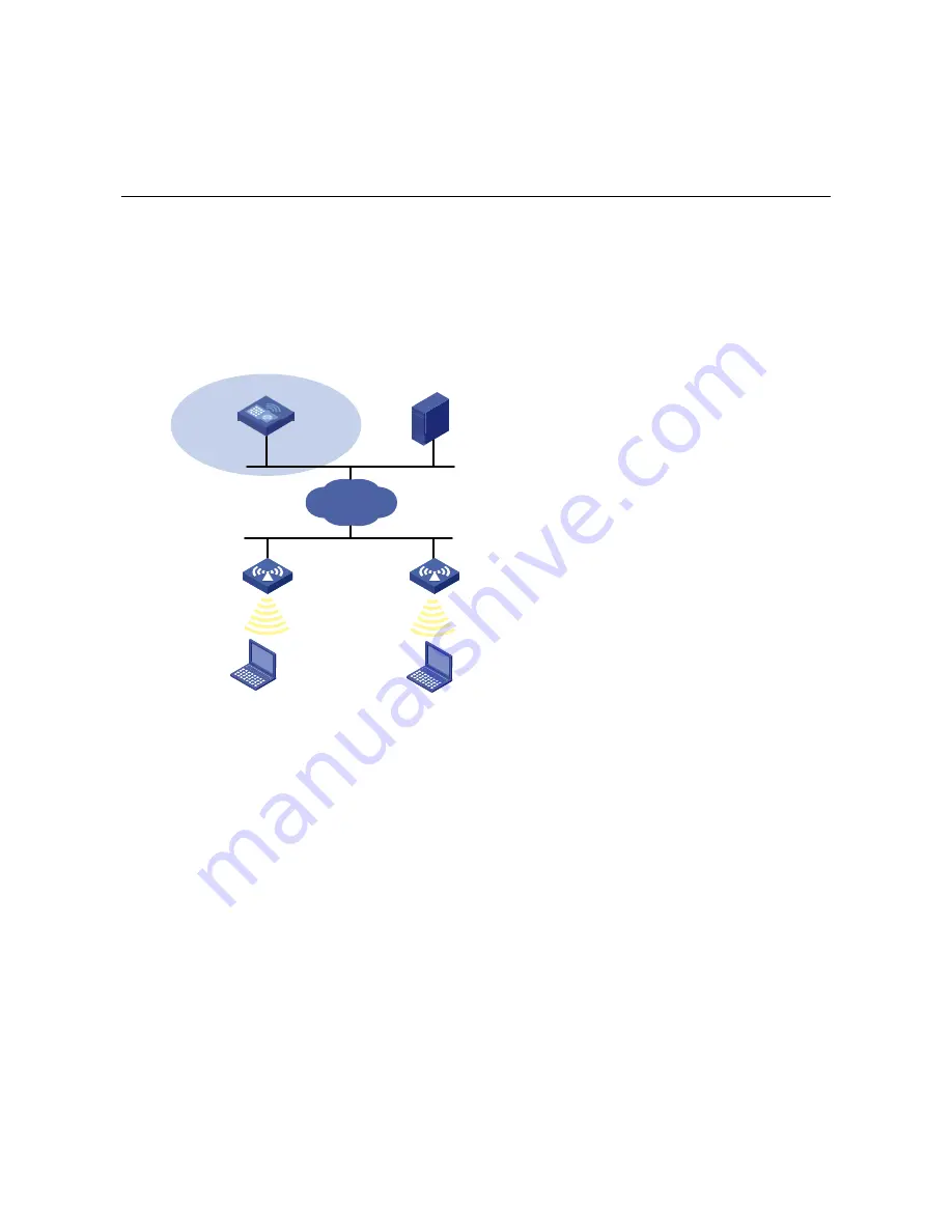
As shown in the following figure, the AC is connected to Switch (Layer 2 or Layer 3) through GE1/0/1,
which can be connected to APs directly or connected to APs over an IP network. Clients can be
connected to the network through the APs to implement WLAN user access.
Figure 2-1
AC networking
AC
GE 1/0/1
Server
AP 1
AP 2
Client A
Client B
Scheme 1
IP network
Access Controller Module Networking
As shown in the following figure, installed with an access controller module, Switch (Layer 2 or Layer 3)
can be connected to APs directly or connected to APs over an IP network. Clients can be connected to
the network through the APs to implement WLAN user access.


