background image


1-2 

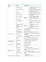
LED 

Status 

Description 

(SYS) 

Slow flashing yellow 

The memory does not exist or system 
initialization has failed. 

Fast flashing yellow 

The extended segment does not exist. 

Off 

The system hardware is faulty or the 
device has no power input. 

Steady green 

BootWare 
stage 

The SDRAM is performing self-test. 

Fast flashing green 

The system software image is being 
decompressed. 

Slow flashing green 

Comware is starting up and the 
system is operating correctly. 

Steady yellow 

The system software image does not 
exist. 

Slow flashing yellow 

The SDRAM has failed the self-test. 

Off 

No power input, or exceptions have 
occurred. 

Fast flashing green (5 
seconds) 

Comware 
stage 

The USB disk completed auto 
configuration. 

Fast flashing yellow (10 
seconds) 

The USB disk has failed auto 
configuration. 

Power button LED 

Fast flashing red 

The power button is being pressed to start up the 
Comware system. 

Slow flashing red 

BIOS is starting up. 

Slow flashing green 

BIOS has started and BootWare is starting up. 

Steady green 

The Comware system has started and the device is 
operating. 

Fast flashing green 

The power button is being pressed to power off the 
Comware system. 

Steady red 

The Comware system is being shutting down. 

Off 

The Comware system has been shut down. 

Power status LED 
(PWR1 or PWR2) 

Steady green 

The power system is operating correctly. 

Off 

No power is being input. 

PoE status LED 

Steady green 

Normal PoE input. 

Flashing green 

Abnormal PoE input. 

Off 

No PoE input. 

Ethernet copper port 
LED 

Steady green 

A 1000 Mbps link is present. 

Flashing green 

The port is receiving or transmitting data at 1000 
Mbps. 

Steady yellow 

A 10/100 Mbps link is present. 

Flashing yellow 

The port is receiving or transmitting data at 10/100 
Mbps. 

Off 

No link is present. 

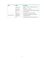
Ethernet fiber port LED 

Steady green 

A 1000 Mbps link is present. 

Summary of Contents for ICT Converged Gateway Series

Page 1: ...H3C MSR3610 I ICT Converged Gateway Series Hardware Information and Specifications New H3C Technologies Co Ltd http www h3c com Document version 6W100 20201231...

Page 2: ...espective owners Notice The information in this document is subject to change without notice All contents in this document including statements information and recommendations are believed to be accur...

Page 3: ...optional x y Braces enclose a set of required syntax choices separated by vertical bars from which you select one x y Square brackets enclose a set of optional syntax choices separated by vertical bar...

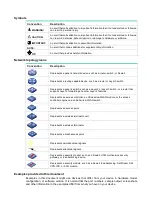
Page 4: ...s a Layer 2 or Layer 3 switch or a router that supports Layer 2 forwarding and other Layer 2 features Represents an access controller a unified wired WLAN module or the access controller engine on a u...

Page 5: ...Documentation feedback You can e mail your comments about product documentation to info h3c com We appreciate your comments...

Page 6: ...nical specifications 1 1 Chassis views 1 1 MSR3610 I DP MSR3610 I XS MSR3610 IE DP MSR3610 IE ES MSR3610 IE XS 1 1 MSR3610 IE EAD 1 2 MSR3610 I IG 3610 IE IG 1 2 Power button 1 3 Technical specificati...

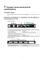
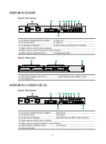
Page 7: ...R3610 IE XS Figure1 1 Front panel 1 AC power receptacles PWR1 and PWR2 2 Drive slot 3 Power button LED 4 USB port 5 Console port CONSOLE 6 Ethernet fiber port SFP0 combo interface 7 Ethernet fiber por...

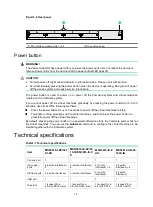
Page 8: ...button HD Figure1 4 Rear panel 1 SIC interface module slots 3 and 4 2 SIC M2 SATA riser modules 1 and 2 3 Grounding screw MSR3610 I IG 3610 IE IG Figure1 5 Front panel 1 AC power receptacles PWR1 and...

Page 9: ...power button for over 3 seconds to power off the virtual machines forcibly Terminate running processes on the virtual machines and then press the power button to gracefully power off the virtual mach...

Page 10: ...Hz Maximum power consumption 54 W 54 W 54 W 54 W Operating temperature Without a drive 0 C to 45 C 32 F to 113 F With a drive 5 C to 40 C 41 F to 104 F Without a drive 0 C to 45 C 32 F to 113 F With a...

Page 11: ...ces that can operate only as Layer 3 Ethernet interfaces Device model Interfaces MSR3610 I DP MSR3610 I XS MS R3610 IE DP MSR3610 IE ES MS R3610 IE XS Combo 0 GE0 SFP0 Combo 1 GE1 SFP1 MSR3610 IE EAD...

Page 12: ...i Contents 1 LEDs 1 1 LEDs 1 1 LED descriptions 1 1...

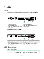
Page 13: ...6 Power button LED 7 Drive LED HD Figure1 2 MSR3610 I IG 3610 IE IG LEDs 1 System status LED SYS 2 Power status LED PWR1 3 Power status LED PWR2 4 PoE status LED 5 LEDs for Ethernet copper ports GE0 t...

Page 14: ...st flashing red The power button is being pressed to start up the Comware system Slow flashing red BIOS is starting up Slow flashing green BIOS has started and BootWare is starting up Steady green The...

Page 15: ...present Flashing yellow The port is receiving or transmitting data at 100 Mbps Off No link is present Hard disk LED HD Steady green The hard disk has completed initialization Flashing green The hard d...

Page 16: ...i Contents 1 Slot arrangement and interface numbering 2...

Page 17: ...ce Table1 1 Slot arrangement and interface numbering Slot arrangement Interface numbering An interface on a SIC interface module is numbered in the x y format x represents the slot number y represents...

Reviews: