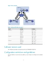
H3C H3C S7500E Series Configuration Examples Download Page 4

Figure 1


Network diagram 


Table 1


Interface and IP address assignment 

Device Interface

IP 

address 

Device A 

Vlan-int10 20.1.1.1/24 


Vlan-int20 2001::1/64 


Tunnel1 3001::1/64 


Tunnel2 4001::1/64 

Device B 

Vlan-int10 30.1.1.1/24 


Vlan-int20 5001::1/64 


Tunnel1 3001::2/64 

Device C 

Vlan-int10 40.1.1.1/24 


Vlan-int20 6001::1/64 


Tunnel2 4001::2/64 


Software version used 

This configuration example was created and verified on S7500E-CMW710-R7150. 

Configuration restrictions and guidelines


For tunnel interfaces to send and receive packets, you must configure a tunnel-type service loopback 

group. 

T

u

n

n

e

l 1

T

u

n

n

e

l 1

T

u

n

n

e

l 2

T

u

n

n

e

l 2

Summary of Contents for H3C S7500E Series

Page 1: ...right 2015 Hangzhou H3C Technologies Co Ltd All rights reserved No part of this manual may be reproduced or transmitted in any form or by any means without prior written consent of Hangzhou H3C Techno...

Page 2: ...tunneling with OSPFv3 1 Network requirements 1 Software version used 2 Configuration restrictions and guidelines 2 Configuration procedures 3 Configuring IPv6 over IPv4 manual tunnels 3 Configuring O...

Page 3: ...of H3C IPv6 over IPv4 manual tunneling and OSPFv3 Example Configuring IPv6 over IPv4 manual tunneling with OSPFv3 Network requirements As shown in Figure 1 in IPv6 networks Device A Device B and Devi...

Page 4: ...1 24 Vlan int20 5001 1 64 Tunnel1 3001 2 64 Device C Vlan int10 40 1 1 1 24 Vlan int20 6001 1 64 Tunnel2 4001 2 64 Software version used This configuration example was created and verified on S7500E C...

Page 5: ...opback group 1 type tunnel Assign GigabitEthernet 1 0 3 to service loopback group 1 DeviceA interface gigabitethernet 1 0 3 DeviceA GigabitEthernet1 0 3 port service loopback group 1 DeviceA GigabitEt...

Page 6: ...ecify VLAN interface 10 as the source interface of Tunnel 1 DeviceB Tunnel1 source vlan interface 10 Specify the destination address for Tunnel 1 DeviceB Tunnel1 destination 20 1 1 1 DeviceB Tunnel1 q...

Page 7: ...spfv3 1 area 0 DeviceA Tunnel2 quit Enable OSPFv3 on VLAN interface 20 DeviceA interface vlan interface 20 DeviceA Vlan interface20 ospfv3 1 area 0 DeviceA Vlan interface20 quit Configure Device B Spe...

Page 8: ...ng statistics for 2001 3 Packets Sent 4 Received 4 Lost 0 0 loss Approximate round trip times in milli seconds Minimum 0ms Maximum 13ms Average 3ms The output shows that the ping operation succeeds Pi...

Page 9: ...lan 10 interface GigabitEthernet1 0 2 port link mode bridge port access vlan 20 interface GigabitEthernet1 0 3 port link mode bridge port service loopback group 1 interface Tunnel1 mode ipv6 ipv4 ospf...

Page 10: ...bridge port access vlan 20 interface GigabitEthernet1 0 3 port link mode bridge port service loopback group 1 interface Tunnel1 mode ipv6 ipv4 ospfv3 1 area 0 0 0 0 source Vlan interface10 destinatio...

Page 11: ...Ethernet1 0 3 port link mode bridge port service loopback group 1 interface Tunnel2 mode ipv6 ipv4 ospfv3 1 area 0 0 0 0 source Vlan interface10 destination 20 1 1 1 ipv6 address 4001 2 64 Related doc...

Reviews: