background image


4-32 

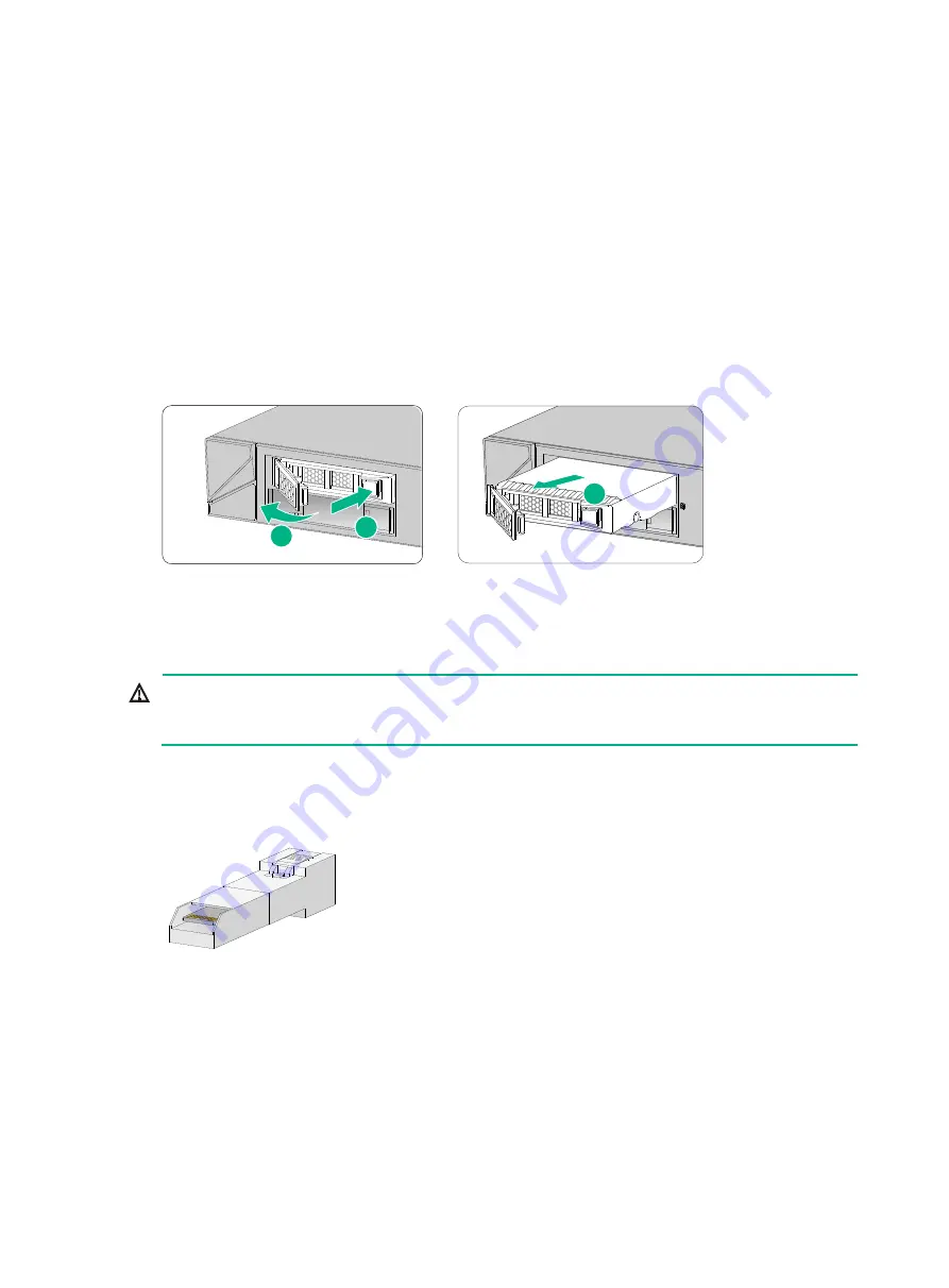
Replacing a drive for other F1000-AI-X0 firewalls than 
F1000-AI-03 and F1000-AI-10 

1. 

Log in to the Web interface. Click the 

Unmount

 button on the 

Storage settings

 page. 

2. 

Wear an ESD wrist strap and make sure it makes good skin contact and is reliably grounded. 

3. 

Press the button on the drive panel to release the locking lever. 

4. 

Hold the locking lever and pull the drive out of the slot. 

5. 

Install a new drive. For the installation procedure, see "

Installing a drive for other firewalls than 

the F1000-AI-30 and F1000-AI-10

." 

If you are not to install a new drive in the slot, install a filler panel in the slot to prevent dust and 
ensure good ventilation. 

Figure4-5 Removing a drive 


Replacing a transceiver module 


WARNING! 

Disconnected optical fibers or transceiver modules might emit invisible laser light. Do not stare into 
beams or view directly with optical instruments when the firewall is operating. 


When you replace a transceiver module, make sure the two transceiver modules connected by the 
same optical fiber are the same type. Do not touch the golden plating of the transceiver module. 

Figure4-6 Transceiver module golden plating 


To replace a transceiver module: 

1. 

Use the 

shutdown

 command in interface view at the CLI to shut down the optical source 

before you remove the fiber connector.  

2. 

Remove the LC connectors with the optical fiber from the transceiver module, and install dust 
caps to the LC connectors.  

3. 

Pivot the clasp of the transceiver module down to the horizontal position, and gently pull the 
transceiver module out.  

1

2

3

Golden 

plating

Summary of Contents for F1000-AI-20

Page 1: ... for an F1000 AI 20 F1000 AI 30 or F1000 AI 50 firewall 16 Installing a power supply for an F1000 AI 60 F1000 AI 70 F1000 AI 80 or F1000 AI 90 firewall 16 Installing an interface module 17 Installing a drive 18 Installing a drive for an F1000 AI 03 or F1000 AI 10 firewall 18 Installing a drive for other firewalls than the F1000 AI 30 and F1000 AI 10 19 Connecting Ethernet cables 19 Connecting a co...

Page 2: ...isplaying software and hardware version information for the firewall 5 34 Displaying electrical label information for the firewall 5 35 Displaying the CPU usage of the firewall 5 35 Displaying the memory usage of the firewall 5 36 Displaying the operational status of power supplies 5 37 Displaying temperature information for the firewall 5 37 Displaying the operational statistics about the firewal...

Page 3: ...information that if not understood or followed can result in data loss data corruption or damage to hardware or software General safety recommendations Do not place the firewall on an unstable case or desk The firewall might be severely damaged in case of a fall Make sure the ground is dry and flat and anti slip measures are in place Keep the chassis and installation tools away from walk areas Kee...

Page 4: ...e laser light Do not stare into beams or view directly with optical instruments when the firewall is operating Before you disconnect the fiber connector execute the shutdown command in interface view to disable the optical source Install dust caps to disconnected optical fiber connectors and ports on disconnected transceiver modules to avoid damage caused by built up dust Insert a dust plug into e...

Page 5: ...ment room Lasting high relative humidity can cause poor insulation electricity leakage mechanical property change of materials and metal corrosion Lasting low relative humidity can cause washer contraction and ESD and bring problems including loose captive screws and circuit failure High temperature can accelerate the aging of insulation materials and significantly lower the reliability and lifesp...

Page 6: ...g Ensure a minimum clearance of 100 mm 3 94 in around the air inlet and outlet vents of the chassis 19 inch rack mounting Ensure a minimum clearance of 80 mm 3 15 in around the air inlet and outlet vents of the chassis and a distance of 1U 44 45 mm or 1 75 in between the chassis and other devices Make sure the installation site has a good cooling system The F1000 AI 03 firewall uses passive coolin...

Page 7: ...attern of capacitance coupling Inductance coupling Electromagnetic wave radiation Common impedance including the grounding system coupling To prevent EMI use the following guidelines If AC power is used use a single phase three wire power receptacle with protection earth PE to filter interference from the power grid Keep the firewall far away from radio transmitting stations radar stations and hig...

Page 8: ... All installation tools are user supplied Flat head screwdriver Phillips screwdriver Needle nose pliers Marker Diagonal pliers ESD wrist strap Accessories Mounting bracket for the F1000 AI 03 Mounting bracket for the F1000 AI 10 Mounting brackets including M4 shoulder screw for other firewalls than the F1000 AI 03 F1000 AI 10 screw M6 screw provided with the F1000 AI 03 F1000 AI 10 and user suppli...

Page 9: ...uipment workbench and rack are reliably grounded The equipment room is dust proof The humidity and temperature are at an acceptable level Wear an ESD wrist strap and make sure it makes good skin contact and is reliably grounded when installing removable components Put the removed interface modules away on an ESD workbench with the PCB upward or put them in ESD bags for future use Touch only the ed...

Page 10: ...e firewall and installation accessories The size of the rack is appropriate for the firewall The front and rear of the rack are a minimum of 0 8 m 31 50 in away from walls or other devices Safety precautions The firewall is far away from any moist area and heat source The emergency power switch in the equipment room is located Tools and accessories Installation accessories supplied with the firewa...

Page 11: ...irewall and rack are reliably grounded and you wear an ESD wrist strap 5 Installing power supplies Before you install a power supply make sure the power supply is not connected to any power source and the grounding cable of the firewall is connected reliably 6 Installing an interface module Install compatible interface modules on the firewall 7 Installing a drive Install compatible drives on the f...

Page 12: ...the firewall CAUTION For adequate heat dissipation ensure a minimum clearance of 80 mm 3 15 in around the air inlet and outlet vents of the chassis and a distance of 1U 44 45 mm or 1 75 in between the chassis and other devices in the rack As a best practice use a rack shelf together with the mounting brackets to support the weight of the chassis Rack mounting the firewall by using front mounting b...

Page 13: ...sides of the firewall with M4 screws provided with the firewall Figure2 3 Attaching the front mounting brackets to the firewall 6 Mount the firewall in the rack Use M6 screws to secure the mounting brackets to the front rack posts Figure2 4 Mounting the firewall in the rack 1 2 3 ...

Page 14: ...tallation positions on the front rack posts and use a rear mounting bracket to mark the installation positions on the rear rack posts 4 Install cage nuts Figure2 5 Installing cage nuts 5 Attach the front mounting brackets and shoulder screws to both sides of the firewall with M4 screws provided with the firewall Figure2 6 Attaching mounting brackets and shoulder screws to the firewall 6 Attach the...

Page 15: ...mm 6 02 in between the rear rack posts and the interior side of the rack door Figure2 7 Attaching the rear mounting brackets to the rear rack posts with the wide flange inside the rack Figure2 8 Attaching the rear mounting brackets to the rear rack posts with the wide flange outside the rack 7 Mount the firewall in the rack Use M6 screws to secure the mounting brackets to the front rack posts and ...

Page 16: ...the firewall grounding cable is crucial to lightning protection and EMI protection Do not connect the firewall grounding cable to a fire main or lightning rod You can ground the firewall in one of the following ways depending on the grounding conditions available at the installation site Grounding the firewall with a grounding strip If a grounding strip is available at the installation site connec...

Page 17: ... the firewall chassis 2 Attach the grounding screw to the ring terminal of the grounding cable 3 Use a Phillips screwdriver to fasten the grounding screw into the grounding hole on the firewall 4 Remove the grounding screw from the grounding point on the rack 5 Attach the ring terminal at the other end of the grounding cable to the grounding point on the rack Figure2 12 Grounding the firewall with...

Page 18: ...of the module with one hand and supporting the module bottom with the other slide the power supply slowly into the slot along the guide rails 4 Use a Phillips screwdriver to fasten the captive screws on the power supply to secure the power supply in place Figure2 14 Installing a power supply for an F1000 AI 20 F1000 AI 30 or F1000 AI 50 firewall Installing a power supply for an F1000 AI 60 F1000 A...

Page 19: ...as a best practice If you have installed an interface module in a lower slot you must press down the ejector levers of the interface module while inserting it into an upper slot Only the F1000 AI 20 F1000 AI 30 F1000 AI 50 F1000 AI 60 F1000 AI 70 F1000 AI 80 and F1000 AI 90 firewalls support interface modules No interface modules are provided with the firewall Purchase them as needed For interface...

Page 20: ...and do not squeeze vibrate or strike a drive Install a filler panel in empty drive slots to prevent dust and ESD damage IMPORTANT The device does not come with any drives and cannot recognize drives from other vendors Purchase drives from H3C as needed Before using the drive execute the fdisk and format commands from the CLI to partition and format the drive For more information about the commands...

Page 21: ...alls than the F1000 AI 30 and F1000 AI 10 Connecting Ethernet cables Connecting a copper Ethernet port You can use either a straight through or a cross over network cable For more information about Ethernet twisted pair cables see Appendix C Cables To connect a copper Ethernet port 1 Connect one end of the Ethernet cable to the copper Ethernet port of the firewall and the other end to the Ethernet...

Page 22: ...stall a transceiver module connected with a fiber into a fiber port To connect an optical fiber first install the transceiver module in the fiber port and then connect the fiber Insert a dust plug into any open fiber port Make sure the Tx and Rx ports on a transceiver module are connected to the Rx and Tx ports on the peer end respectively The firewall supports GE SFP transceiver modules and 10GE ...

Page 23: ...ng an optical fiber Connecting power cords CAUTION Make sure the grounding cable of the firewall is correctly connected and the power source is powered off before connecting the power cord Connecting an AC power cord Connecting an AC power cord for an F1000 AI 03 or F1000 AI 10 firewall 1 Attach the hooks of the power cord retainer clip into the holes on the top of the AC input power receptacle an...

Page 24: ...ct the other end of the power cord to an AC power source Figure2 25 Connecting an AC power cord using a power cord retainer clip to secure the power cord Figure2 26 Connecting an AC power cord using a releasable cable tie to secure the power cord Connecting an AC power cord for an F1000 AI 60 F1000 AI 70 F1000 AI 80 or F1000 AI 90 firewall 1 Connect the female connector of the AC power cord to the...

Page 25: ...cord connector 3 Use a releasable cable tie to secure the power cord to the handle 4 Connect the other end of the power cord to a DC power source Figure2 28 Connecting a DC power cord Connecting a high voltage DC power cord Only the F1000 AI 60 F1000 AI 70 F1000 AI 80 and F1000 AI 90 firewalls support high voltage DC power cords The connection procedure is similar for high voltage DC power cords a...

Page 26: ... firewall and its components are installed securely The screws are fastened tightly The power source specifications are as required by the firewall The grounding cable and power cords are connected correctly ...

Page 27: ...modules if any are installed correctly Starting the firewall and observing the initial startup conditions 1 Turn on the circuit breakers to power on the firewall 2 Observe the initial startup conditions to verify that the firewall starts up correctly The LEDs on the front panel indicate that the device is operating correctly For more information about LEDs see Appendix B LEDs The fan blades are ro...

Page 28: ...swer test for HMAC SHA1 passed Known answer test for HMAC SHA224 passed Known answer test for HMAC SHA256 passed Known answer test for HMAC SHA384 passed Known answer test for HMAC SHA512 passed Known answer test for AES passed Known answer test for RSA signature verification passed Known answer test for RSA encrypt decrypt passed Known answer test for DSA signature verification passed Known answe...

Page 29: ...ation guides and command references for the firewall Logging in from the Web interface Logging in from the serial console port or micro USB console port Logging in through Telnet Logging in from the Web interface At the first login from the Web interface you can use the default account or use an account created from the CLI Table3 1 shows the default Web interface login information Table3 1 Defaul...

Page 30: ...sole port and micro USB console port By default the firewall uses the scheme access authentication mode The username and password are both admin To configure and manage the firewall through the serial console port or micro USB console port you must run a terminal emulator program TeraTermPro or PuTTY on your configuration terminal and configure the following settings for the terminal For more info...

Page 31: ...takes a DC power supply as an example To replace a power supply for an F1000 AI 20 F1000 AI 30 or F1000 AI 50 firewall 1 Face the rear panel of the firewall 2 Use a Phillips screwdriver to loosen the captive screw of the power supply 3 Hold the power supply with one hand and pull the power supply part way out of the slot 4 Supporting the bottom of the power supply with the other hand gently pull t...

Page 32: ...F1000 AI 70 F1000 AI 80 or F1000 AI 90 firewall If you are not to install a new power supply install a filler panel in the slot to ensure good ventilation in the firewall Figure4 2 Removing a power supply from an F1000 AI 60 F1000 AI 70 F1000 AI 80 or F1000 AI 90 firewall Replacing an interface module CAUTION Do not hot swap interface modules Power off the firewall before you replace an interface ...

Page 33: ... damage execute the umount command from the CLI to unmount all the file systems before removing a drive Do not hot swap drives Replacing a drive for an F1000 AI 03 or F1000 AI 10 firewall 1 Log in to the Web interface Click the Unmount button on the Storage settings page 2 Wear an ESD wrist strap and make sure it makes good skin contact and is reliably grounded 3 Pull the drive slowly out of the s...

Page 34: ...drive Replacing a transceiver module WARNING Disconnected optical fibers or transceiver modules might emit invisible laser light Do not stare into beams or view directly with optical instruments when the firewall is operating When you replace a transceiver module make sure the two transceiver modules connected by the same optical fiber are the same type Do not touch the golden plating of the trans...

Page 35: ...aps to the removed transceiver module and put it into the package 5 Install a new transceiver module If you do not install a new transceiver module in the slot install a dust cap For information about installing a transceiver module see Connecting a fiber port 1 2 ...

Page 36: ..._B 1 0 CFCard Num 0 Displaying software and hardware version information for the firewall Use the display version command to display software and hardware version information for the firewall Sysname display version H3C Comware Software Version 7 1 064 Ess 9345 Copyright c 2004 2019 New H3C Technologies Co Ltd All rights reserved H3C SecPath F1000 AI 50 uptime is 0 weeks 3 days 1 hour 3 minutes La...

Page 37: ...ESS 487A DA95 91F3 MANUFACTURING_DATE 2019 04 29 VENDOR_NAME H3C Fan 0 The operation is not supported on the specified fan Fan 1 The operation is not supported on the specified fan Fan 2 The operation is not supported on the specified fan Fan 3 The operation is not supported on the specified fan Power 1 The operation is not supported on the specified power Table5 1 Output description Field Descrip...

Page 38: ...ll Sysname display memory Memory statistics are measured in KB Slot 1 Total Used Free Shared Buffers Cached FreeRatio Mem 14309392 1775520 12533872 0 2644 298664 87 9 Buffers Cache 1474212 12835180 Swap 0 0 0 Table5 3 Output description Field Description Slot Slot number of the interface module Mem Memory usage information Total Total size of the physical memory space that can be allocated The mem...

Page 39: ...tion Abnormal The power supply has failed Displaying temperature information for the firewall Use the display environment command to display the temperature information of the firewall Sysname display environment System Temperature information degree centigrade Slot Sensor Temperature LowerLimit Warning UpperLimit Alarm UpperLimit Shutdown UpperLimit 1 inflow 1 28 2 52 60 NA 1 outflow 1 31 0 55 65...

Page 40: ...n one time you can execute the display diagnostic information command in any view to display or save the operational statistics of multiple functional modules of the firewall Save the operational statistics of each functional module of the firewall Sysname display diagnostic information Save or display diagnostic information Y save N display Y N y Please input the file name gz flash diag gz Diagno...

Page 41: ...nterface display transceiver alarm interface interface type interface number Available for all transceiver modules Rebooting the firewall CAUTION If the main system software image file does not exist do not use the reboot command to reboot the firewall Specify the main system software image file first and then reboot the firewall The precision of the rebooting timer is 1 minute 1 minute before the...

Page 42: ...and Remarks Enable the scheduled reboot function Enable the scheduled reboot function and specify a specific reboot time and date scheduler reboot at Enable the scheduled reboot function and specify a reboot waiting time scheduler reboot delay Use either approach The scheduled reboot function is disabled by default Available in user view ...

Page 43: ...ssue 1 Verify that the power supply system is operating correctly 2 Verify that the serial console cable or micro USB console cable is correctly connected 3 Verify that the serial console cable or micro USB console cable is connected to the serial port configured on the configuration terminal 4 Verify that the configuration terminal parameters are configured as follows Baud rate 9600 Data bits 8 P...

Page 44: ...el high temperature alarm threshold power off the firewall immediately and contact your local sales agent 5 If the issue persists contact your local sales agent Software loading failure Symptom Software loading fails and the system runs the software of the previous version Solution To solve the issue 1 Verify that the physical ports are correctly connected 2 Verify that no parameter is configured ...

Reviews: