background image


11 

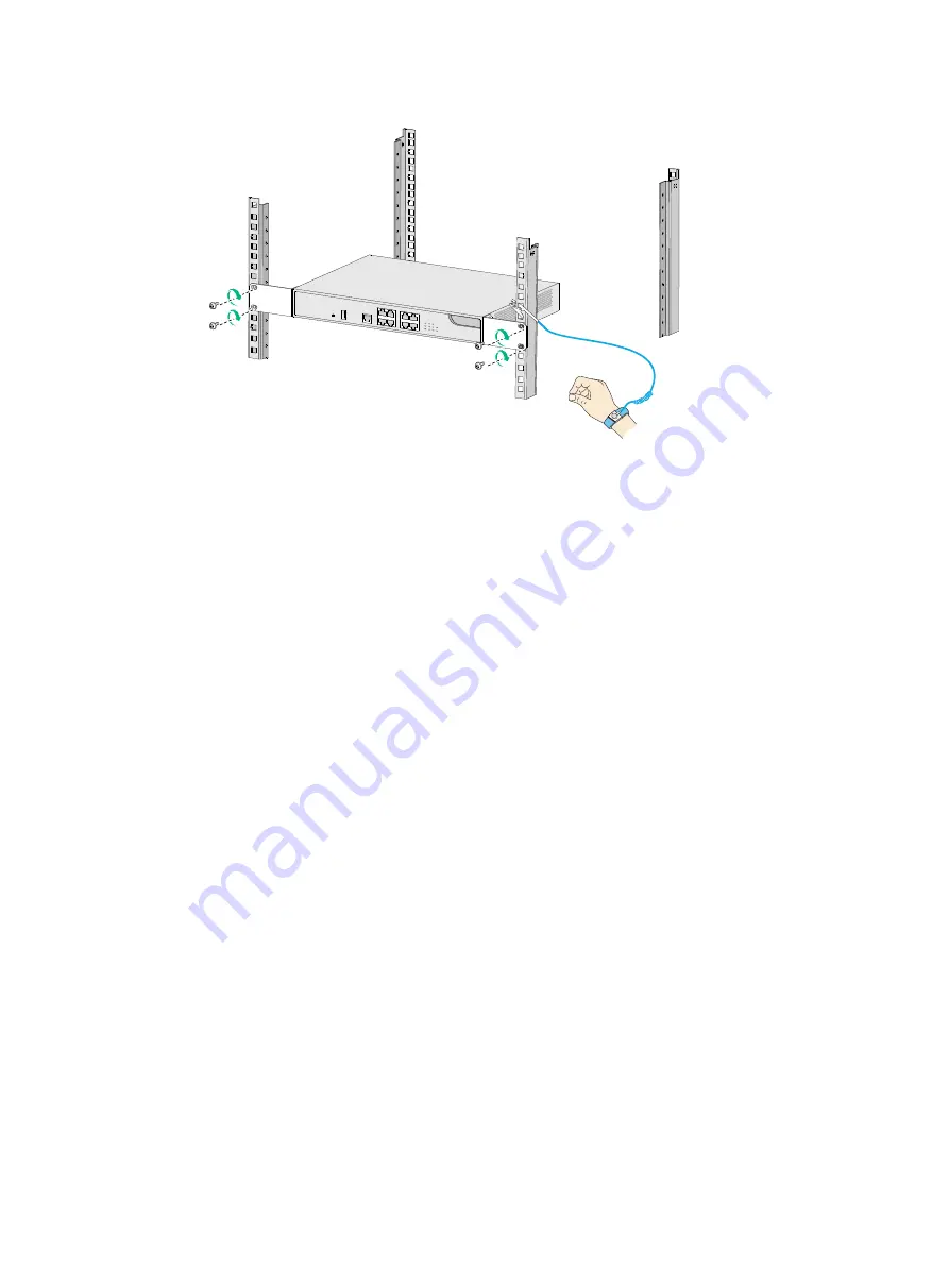
Figure1-7 Mounting the firewall in the rack 


Mount the firewall on a wall 

1. 

Unpack the firewall and accessories. 

2. 

Mark two installation holes spaced 102 mm (4.02 in) apart on the wall. 

3. 

Drill holes with a diameter of 6 mm (0.24 in) and a depth of 22 mm (0.87 in) at the marked 
locations. 

4. 

Hammer a screw anchor into each hole and drive a screw into each screw anchor, leaving 1.5 
mm (0.06 in) of the screw exposed to hang the firewall on. 

Make sure the screw anchors and screws are secured in place. 

5. 

Hold the firewall with its front panel facing downwards, align the installation holes on the firewall 
with the screws on the wall, and set the holes over the screws. 

6. 

Verify that the firewall is securely mounted on the wall. Do not let go of your hands from the 
firewall until you are sure of the secure mounting of the firewall. 

7. 

Connect the firewall to the grounding facility of the building. 

Summary of Contents for F100-C-A3-W

Page 1: ...H3C SecPath F100 C A W Firewalls Installation Guide New H3C Technologies Co Ltd http www h3c com Document version 6W101 20200713 ...

Page 2: ...respective owners Notice The information in this document is subject to change without notice All contents in this document including statements information and recommendations are believed to be accurate but they are presented without warranty of any kind express or implied H3C shall not be liable for technical or editorial errors or omissions contained herein Environmental protection This produc...

Page 3: ...ntax choices keywords or arguments that are optional x y Braces enclose a set of required syntax choices separated by vertical bars from which you select one x y Square brackets enclose a set of optional syntax choices separated by vertical bars from which you select one or none x y Asterisk marked braces enclose a set of required syntax choices separated by vertical bars from which you select a m...

Page 4: ...as a Layer 2 or Layer 3 switch or a router that supports Layer 2 forwarding and other Layer 2 features Represents an access controller a unified wired WLAN module or the access controller engine on a unified wired WLAN switch Represents an access point Represents a wireless terminator unit Represents a wireless terminator Represents a mesh access point Represents omnidirectional signals Represents...

Page 5: ...Documentation feedback You can e mail your comments about product documentation to info h3c com We appreciate your comments ...

Page 6: ...onal Installing a lightning arrester for an AC power module 15 Installing a Wi Fi antenna 15 Installing a 4G antenna 15 Connecting Ethernet cables 16 Connecting an AC power cord 17 Verifying the installation 17 Accessing the firewall 18 Setting up the configuration environment and configuring terminal parameters 18 Starting the firewall 18 Pre start checking 18 Starting the firewall and observing ...

Page 7: ...l specifications 28 Chassis views 28 F100 C A3 W F100 C A5 W 28 F100 C A6 WL 29 Technical specifications 30 Dimensions and weights 30 Storage media 30 Power consumption 30 Power specifications 30 Port specifications 30 Appendix B LEDs 33 Appendix C Cables 35 Console cable 35 Ethernet twisted pair cable 35 Introduction 35 Making an Ethernet twisted pair cable 38 ...

Page 8: ...an result in data loss data corruption or damage to hardware or software General safety recommendations Make sure the installation position is flat vibration free and away from electromagnetic interferences ESD and anti slip measures are in place Do not place the firewall on an unstable case or desk The firewall might be severely damaged in case of a fall Keep the chassis and installation tools aw...

Page 9: ...pack the firewall carefully to avoid firewall damage Unpack the firewall at least half an hour and power on the firewall at least two hours after you move it from a place below 0 C 32 F to the equipment room This prevents condensation and even damage to the firewall Before you move the firewall remove all cables and mounting brackets For long distance transportation remove all removable components...

Page 10: ...nsing Cleanliness Dust buildup on the chassis might result in electrostatic adsorption which causes poor contact of metal components and contact points especially when indoor relative humidity is low In the worst case electrostatic adsorption can cause communication failure Table1 2 Dust concentration limit in the equipment room Substance Concentration limit particles m 3 Dust particles 3 10 4 No ...

Page 11: ...ase one yourself Before you attach an ESD wrist strap make sure the rack or the workbench is reliably grounded To attach the ESD wrist strap 1 Wear the wrist strap on your wrist 2 Lock the wrist strap tight around your wrist to keep good contact with the skin 3 Secure the wrist strap lock and the alligator clip lock together 4 Attach the alligator clip to the rack or the workbench Figure1 2 Attach...

Page 12: ... the lightning protection capability of the power module To prevent signal ports from getting damaged by overvoltage or overcurrent caused by lightning strikes route interface cables only indoors If part of the network cable of an Ethernet port must be routed outdoors connect a lightning arrester to the cable before you plug the cable into the port Power supply Verify that the power system at the ...

Page 13: ...is available at the installation site Ambient temperature Operating 0 C to 45 C 32 F to 113 F Storage 40 C to 70 C 40 F to 158 F Ambient humidity 5 RH to 95 RH noncondensing Cleanness Dust concentration 3 10 4 particles m 3 No dust on desk within three days ESD prevention The equipment workbench and rack are reliably grounded The equipment room is dust proof The humidity and temperature are at an ...

Page 14: ...uding the power input method and rated input voltage Rack mounting requirements Make sure the cabinet is equipped with a good ventilation system The rack is sturdy enough to support the weight of the firewall and installation accessories The size of the rack is appropriate for the firewall The front and rear of the rack are a minimum of 0 8 m 31 50 in away from walls or other devices Safety precau...

Page 15: ...he same for the H3C SecPath F100 C A W series firewalls This document uses the F100 C A6 WL firewall as an example Figure1 3 Firewall installation flow Determine the installation position Mount the firewall on a workbench Mount the firewall in a 19 inch rack Ground the firewall Install Wi Fi antennas Connect Ethernet cables Connect the power cord Verify the installation Install optional components...

Page 16: ...ssis bottom with a dry cloth 3 Attach the four rubber feet to the round holes in the chassis bottom 4 Place the firewall with upside up on the workbench Figure1 4 Mounting the firewall on a workbench Installing the firewall in a standard 19 inch rack WARNING To avoid bodily injury and device damage use a minimum of two persons to rack mount the firewall CAUTION For adequate heat dissipation ensure...

Page 17: ... provided M4 mounting bracket screws to secure the mounting brackets to both sides of the firewall Figure1 6 Securing mounting brackets to the firewall 5 Mount the firewall in the rack Use M6 rack screws to secure the mounting brackets to the front rack posts 1 2 3 ...

Page 18: ...nto each screw anchor leaving 1 5 mm 0 06 in of the screw exposed to hang the firewall on Make sure the screw anchors and screws are secured in place 5 Hold the firewall with its front panel facing downwards align the installation holes on the firewall with the screws on the wall and set the holes over the screws 6 Verify that the firewall is securely mounted on the wall Do not let go of your hand...

Page 19: ...ding conditions available at the installation site Grounding the firewall with a grounding strip If a grounding strip is available at the installation site connect the grounding cable through the grounding strip To connect the grounding cable 1 Remove the grounding screw from the firewall chassis 2 Attach the grounding screw to the ring terminal of the grounding cable 3 Use a Phillips screwdriver ...

Page 20: ...rminal of the grounding cable 3 Use a Phillips screwdriver to fasten the grounding screw into the grounding hole on the firewall 4 Remove the grounding screw from the grounding point on the rack 5 Use needle nose pliers to bend a hook at the other end of the grounding cable Attach the hook to the grounding point and secure the hook with the screw Figure1 10 Grounding the firewall with the groundin...

Page 21: ...lace 3 Reinstall the cover and fasten the screw on the cover Figure1 11 Installing a SIM card If you want to replace the SIM card perform the following steps 1 Remove the cover form the SIM card slot 2 Push the SIM card inward until it pops out Then remove the SIM card from the slot 3 Install a new SIM card If you are not to install a SIM card reinstall the cover over the empty SIM card slot to av...

Page 22: ... the equipment room For more information about how to install and maintain a lightning arrester for AC power modules see the documents provided with the lightning arrester Installing a Wi Fi antenna 1 Face the rear panel of the firewall 2 Attach the Wi Fi antenna to the firewall and fold the antenna to an angle of 90 degrees Figure1 12 Installing a Wi Fi antenna Installing a 4G antenna Only the F1...

Page 23: ...rnet cables The Ethernet copper ports on the firewall support auto MDI MDIX You can use either straight through or cross over network cables to connect the ports For more information about Ethernet twisted pair cables see Ethernet twisted pair cable To connect an Ethernet cable 1 Connect one end of the Ethernet cable to the copper Ethernet port of the firewall and the other end to the Ethernet por...

Page 24: ...he AC input power receptacle on the firewall 3 Pull the power cord retainer clip downwards and secure the connector to the power receptacle 4 Connect the other end of the power cord to an AC power source Figure1 15 Connecting an AC power cord Verifying the installation Verify the following items to ensure correct installation There is enough space for heat dissipation around the firewall The firew...

Page 25: ...ering on the firewall so you can quickly shut power off when an electrical accident occurs Before powering on the firewall verify that the following conditions are met The power cord and grounding cable are correctly connected The power source specifications meet the firewall requirements The firewall is connected correctly to a configuration terminal a PC for example The configuration terminal ha...

Page 26: ...0 boot E9524P11 bin Done Image file flash f1010fww cmw710 boot E9524P11 bin is self decompressing Done System image is starting Cryptographic algorithms tests passed Line con0 is available Press ENTER to get started Press Enter to access user view of the firewall NOTE To access the EXTENDED BOOTWARE menu press Ctrl B within four seconds at the prompt Press Ctrl B to access EXTENDED BOOTWARE MENU I...

Page 27: ...e PC and the firewall are reachable to each other The PC must use a different IP address than the Ethernet management interface 3 Start a browser enter 192 168 0 1 in the address bar and press Enter 4 Enter the default username admin and password admin and then click Login Logging in from the console port To log in from the console port see Setting up the configuration environment and configuring ...

Page 28: ...ing the software and hardware version information of the firewall Use the display version command to display the software and hardware version information of the firewall Sysname display version H3C Comware Software Version 7 1 064 Alpha 9601P03 Copyright c 2004 2018 New H3C Technologies Co Ltd All rights reserved H3C SecPath F100 C A6 WL uptime is 1 week 4 days 2 hours 47 minutes Boot image flash...

Page 29: ...name DEVICE_SERIAL_NUMBER Firewall serial number MAC_ADDRESS MAC address of the firewall MANUFACTURING_DATE Manufacturing date of the firewall VENDOR_NAME Vendor name Displaying the CPU usage of the firewall Use the display cpu usage command to display the CPU usage of the firewall Sysname display cpu usage Slot 1 CPU 0 CPU usage 3 in last 5 seconds 3 in last 1 minute 3 in last 5 minutes Table1 8 ...

Page 30: ...ts Part 1 is used for kernel codes kernel management and ISSU functions Part 2 can be allocated and used for such tasks as running service modules and storing files The size of part 2 equals the total size minus the size of part 1 Used Used physical memory Free Free physical memory Shared Physical memory shared by processes Buffers Physical memory used for buffers Cached Physical memory used for c...

Page 31: ...atistics of multiple functional modules of the firewall Save the operational statistics of each functional module of the firewall Sysname display diagnostic information Save or display diagnostic information Y save N display Y N y Please input the file name tar gz flash diag tar gz Diagnostic information is outputting to flash diag tar gz Please wait Save successfully To view the diag gz file a Ex...

Page 32: ... at the CLI You can set a time at which the firewall can automatically reboot or set a delay so that the firewall can automatically reboot within the delay Power on the firewall after powering it off which is also called hard reboot or cold start H3C does not recommend that you use this method because it might cause data loss and hardware damages To reboot the firewall immediately Task Command Rem...

Page 33: ...othing or garbled text when the firewall is powered on Solution To resolve the issue 1 Verify that the power system is operating correctly 2 Verify that the console cable is correctly connected 3 Verify that the console cable is connected to the serial port configured on the configuration terminal 4 Verify that the configuration terminal parameters are configured as follows Baud rate 9600 Data bit...

Page 34: ...xamine the software loading process displayed on the TeraTermPro or PuTTY for errors Possible errors include Inconsistent baud rates configured for XMODEM and the TeraTermPro or PuTTY Incorrect IP address software name or TFTP serve path for TFTP Incorrect IP address software name username or password for FTP 3 If the issue persists contact your local sales agent ...

Page 35: ...l 1 Reset button 2 USB port 3 Console port 4 10 100 1000BASE T copper ports 5 LEDs 6 Management Ethernet port GE1 0 0 Rear panel The F100 C A3 W F100 C A5 W firewall provides one AC input power receptacle and one WLAN module on the rear panel Figure1 17 Rear panel 1 Grounding screw 2 AC input power receptacle 3 WLAN module 4 Wi Fi antenna connector 0 5 Wi Fi antenna connector 1 6 WLAN module statu...

Page 36: ...nagement Ethernet port GE1 0 0 Rear panel The F100 C A6 WL firewall provides one AC input power receptacle two 4G antenna ports one SIM card slot and one WLAN module Figure1 19 Rear panel 1 Grounding screw 2 AC input power receptacle 3 4G antenna connector 1 4 4G antenna connector 2 5 WLAN module 6 Wi Fi antenna connector 0 7 Wi Fi antenna connector 1 8 WLAN module status LED 9 WLAN module console...

Page 37: ...s Item Specification Flash 16MB NOR flash 512MB NAND flash Memory 2GB DDR3 Power consumption Table1 13 Power consumption Model System power consumption F100 C A3 W F100 C A5 W 25 W F100 C A6 WL 30 W Power specifications Table1 14 Power specifications Item Specification Rated input voltage range 100 VAC to 240 VAC 50 Hz or 60 Hz Maximum input current 1 A Maximum power 36 W Port specifications Ports...

Page 38: ... 49 21 ft Services Connection to an ASCII terminal Connection to the serial port of a local PC running the terminal emulation program CLI GE copper port Table1 17 GE copper port specifications Item Specification Connector RJ 45 Standard compliance 802 3 802 3u and 802 3ab Auto MDI MDIX Supported Cable type Category 5 or above twisted pair cable Transmission distance 100 m 328 08 ft Data rate and d...

Page 39: ... antenna connectors and is compliant with 802 11a b g n ac It supports 2 4 GHz and 5 GHz bands Table1 18 WLAN module ports Item Specification Connector RJ 45 Port One console port Port standard Console port RS EIA 232 RF interface Radio 1 5 GHz MIMO 1 1 Radio 2 2 4 GHz MIMO 2 2 Cable Console port Common asynchronous serial port cable ...

Page 40: ...ered on or has failed Slow flashing green The firewall is operating correctly Fast flashing green The firewall is loading software Power status LED PWR Off The power system is faulty Steady green The power system is operating correctly 4G module LED LTE Off The 4G module is faulty or in airplane mode Flashing green 1 Hz The 4G module is searching for a network Flashing green 0 3 Hz The 4G module h...

Page 41: ...34 LED Mark Status Description Alternating between yellow and amber Both the 2 4 GHz and 5 GHz radios have client access ...

Page 42: ...Ethernet twisted pair cable consists of four pairs of insulated copper wires twisted together Every wire uses a different color and has a diameter of about 1 mm 0 04 in A pair of twisted copper cables can cancel the electromagnetic radiation of each other and reduce interference of external sources An Ethernet twisted pair cable mainly transmits analog signals and is advantageous in transmitting d...

Page 43: ...although they provide better EMI prevention performance than UTPs so in most LANs UTPs are commonly used An Ethernet twisted pair cable connects network devices through the RJ 45 connectors at the two ends Figure1 21 shows the pinouts of an RJ 45 connector Figure1 21 RJ 45 connector pinout NOTE The RJ 45 Ethernet ports of the firewall use category 5 or higher Ethernet twisted pair cables for conne...

Page 44: ...ts Pin 10BASE T 100BASE TX 1000BASE T Signal Function Signal Function 1 Tx Sends data BIDA Bi directional data cable A Straight through cable white orange orange white green blue white blue green white brown brown 1 2 3 4 5 6 7 8 white orange orange white green blue white blue green white brown brown 1 2 3 4 5 6 7 8 Crossover cable white orange orange white green green white orange orange white gr...

Page 45: ...onal data cable C 8 Reserved N A BIDC Bi directional data cable C To ensure normal communication the pins for sending data on one port must correspond to the pins for receiving data on the peer port When both of the ports on the two devices are MDI or MDIX use a crossover Ethernet cable when one port is MDI and the other is MDIX use a straight through Ethernet cable To summarize straight through a...

Page 46: ...h one another Insert the wires into the RJ 45 connector and make sure the wires extend to the front of the RJ 45 connector and make good contact with the metal contacts in the RJ 45 connector and in the correct order 5 Crimp the RJ 45 connector with the crimping tool until you hear a click 6 Use a cable tester to verify the connectivity of the cable ...

Reviews: