background image

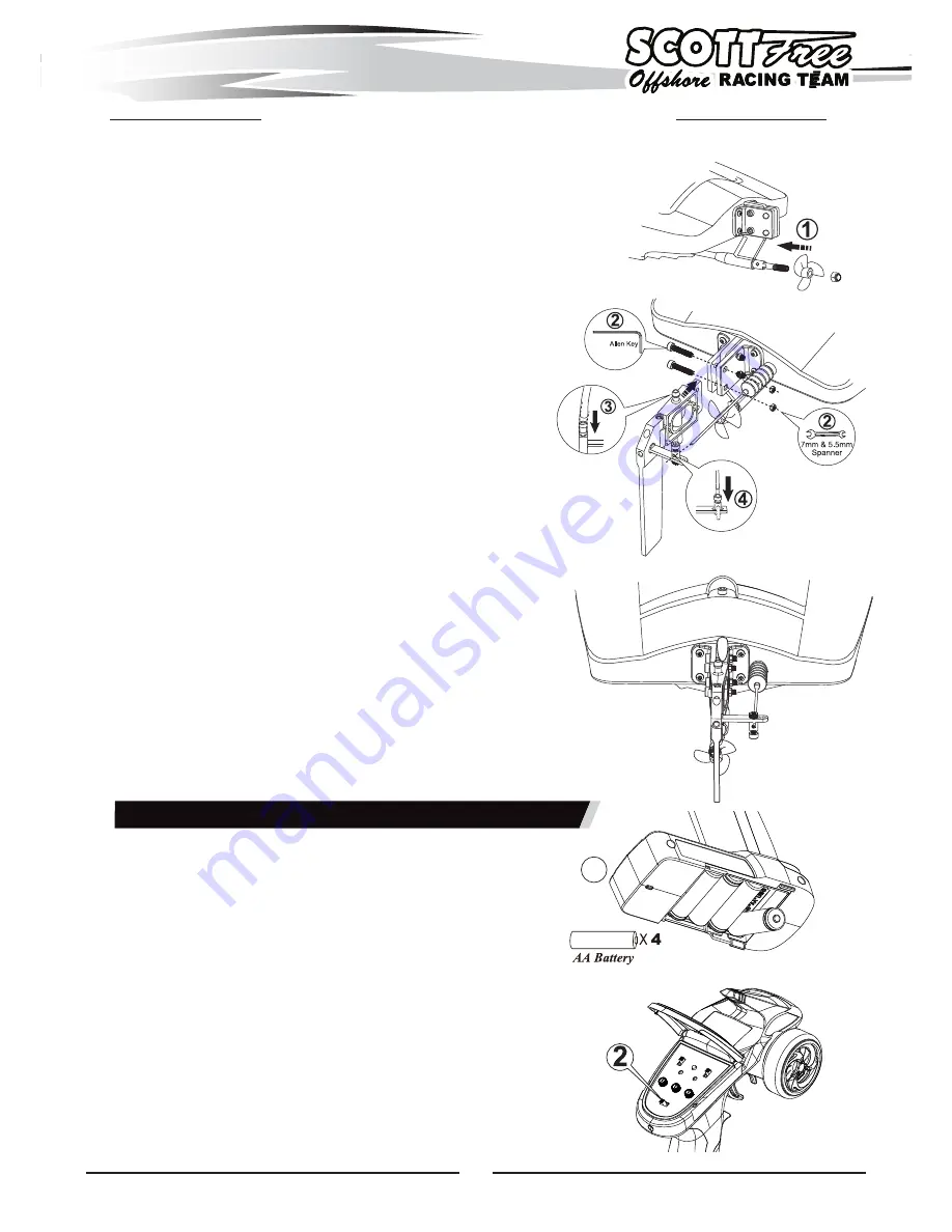
installing the rudder and propeller

Concerning the package safety, the rudder and propeller are not 
pre-installed. They are packed well in the kits bag. Follow the 
belowing steps to install them by yourself easily.

1. Loosen the screw on the propeller shaft by 7mm Spanner, put 

the propeller in then retighten the screw.

2. Insert the rudder support into the support which is already 

installed on the rear of hull. Thread the two pcs of M3 screw in, 
Apply two pcs of M3 nut on the screws, retighten the screws 
and nuts by 2.5mm Allen Key and 5.5mm Spanner.

3. Thread the silicone tube in the brass water inlet.

4. Loosen the adjuster on the servo horn so as to push rudder rod 

to thread in the adjuster located in the rudder horn. Make sure 
the rudder centered and then Retighten the two adjuster with 
2.5mm Allen Key.

Rudder Assembly

NOTE:

 Please install rudder and support on the right 

support which is pre-installed on the rear of hull in 
factory. Installing rudder and support on the right 
side is effective for good performance and 
stability.

1

Installing transmitter batteries (RTR version only)

NOTE: 

The transmitter is not water resistant and should 

never come in contact with water.

1. Install four fresh “AA” batteries. Follow the diagram 

located in the bottom of the battery tray for proper battery 
orientation.

2. Turn the transmitter “ON”. 

4

2.5mm

Summary of Contents for Scott Free Offshore

Page 1: ...hless motor included Radio System 2 4G 2CH Digital Proportional Transmitter included w RTR version only Speed Control Water cooled 60A Brushless ESC w BEC included Drive System 4mm Flex Shaft Direct D...

Page 2: ...the following items to operate your H King Marine brushless motor boat We highly need to purchase the following items to operate your H King Marine brushless motor boat Battery Recommendation Two pack...

Page 3: ...at Stand Cable Strap Three Blade Metal Propeller Contents of Set Scottfree Racing Transmitter 3 60A ESC Circuit Cooling System Diagram RECEIVER Please use this diagram to connect water cooling system...

Page 4: ...ne tube in the brass water inlet 4 Loosen the adjuster on the servo horn so as to push rudder rod to thread in the adjuster located in the rudder horn Make sure the rudder centered and then Retighten...

Page 5: ...r of gravity for maximum performance Below are the batteries location inside the hull NOTE There is a water proof rubber ring glued along the slot of hull always make sure it s securely positioned bef...

Page 6: ...plug into BIND VCC port of receiver 2 Power ON the receiver by connecting battery to ESC The receiver s red LED should now be flashing quickly 3 Hold down the BIND button on the transmitter then swit...

Page 7: ...ngle adjustment Rotate ST L knob to the left end point means minimum value 0 right end point means maximum value 100 CAUTION When adjusting this function make sure the direction is in agreement with t...

Page 8: ...water proof marine grease reinstall the flexshaft w prop shaft in reverse order be sure to retighten the two grub screws of coupler NOTE Running the model boat in salt water could cause some parts to...

Reviews: