


6
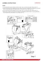
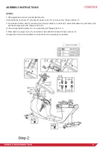
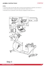
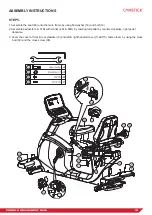
PRO20.0 RECUMBENT BIKE
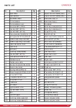
PARTS LIST
No.
Description
Qty.
1
Main frame
1
2
Rear stabilier
1
3
Adjustable wheel
4
4
Front stabilizer
1
5
Front stabilizer cover
2
6
Allen bolt M8*1.25*40L
2
7
Hex bolt M8*1.25*70L
4
7A
Hex bolt M8*1.25*110L
4
8
Curved washer D22xD8.5x1.5T
4
9
Spring washer D15.4xD8.2x2T
12
10L
Middle supporting cover(left)
1
10R
Middle supporting cover(right)
1
11
Upper decorative cover
1
12
Rear cover
1
13
Seat post
1
14
Quick key cable(middle)
2
15
Hex bolt M8*1.25*15L
9
16
Flat washer D16*D8.5*1.2T
29
17
Handlebar psot
1
18
Handle pulse cable
2
19
Bracket for water bottle holder
2
20
Water bottle holder
2
21
Bearing #6004-2RS(C0)
2
22
Waved washer D27*D20.3*0.5T
1
23
Screw M3*0.5*30L
4
24
C-clip D22.5*D18.5*1.2T
2
25
Screw M3*0.5*12L
2
26
Crank axle
1
27
Belt wheel
1
28
Nylon nut M6*1.0*6T
6
29
Hex bolt M6x1.0x15L
4
30
Belt
1
31
Round magnet
1
32L
Quick key cable (upper)(2)
1
32R
Quick key cable(upper)(1)
1
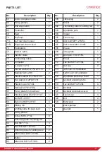
No.
Description
Qty.
33
Upper cover for handle pulse
2
34
Lower cover for handle pulse
2
35L
Membrane keys (+)
1
35R
Membrane keys(-)
1
36
Handlebar
1
37L
Quick key cable(lower)(2)
1
37R
Quick key cable(lower)(1)
1
38
Screw ST4.2*15L
45
39
Bolt M5*0.8*12L
29
40
Back cover for the computer
1
41
Hex bolt M8*1.25*50L
4
42
Rear cover for handlebar
1
43
Front cover for handlebar
1
44
Flat washerD26*D21*1.5T
1
45
Crank cover
2
46
Left chain cover
1
47
Right chain cover
1
48L
Left crank
1
48R
Right crank
1
49
Anti-loose nut M10*1.25*9T
2
50
Screw cover D29*11.5L
2
51L&R Pedal set
1
52
Allen screw M6*1.0*15L
6
53
Flat washer D13*D6.5*1.0T
8
54
Flat washer D13*D6.5*1.0T
4
55
Self-generator system
1
56
Pin
12
57
Nut M5*0.8*5T
1
58
Screw M5*0.8*20L
1
59
Battery connecting cable
1
60
Buffer bar
2
61
Chargeable battery
1
62
Connecting cable(2)
1
63
Upper computer cable
1
64
Upper computer cable
1


