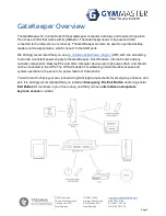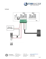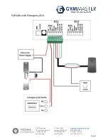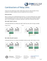
Exit Button Terminals
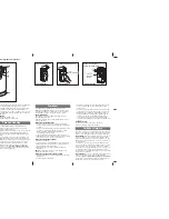
The GateKeeper expects a low level voltage trigger signal in the sensor terminal to activate the
relay to open the door. You can wire a normally-open push button (2 terminals) to Sensor and
GND on the Door 1 or Door 2 socket, refer to the
You need to enable the push button sensor in the door setting page in GymMaster at Settings ->
Door and Readers -> [Specified Door].
RFID Reader Sockets
The rear of the GateKeeper has two sockets. Up to 2 door readers can be connected. Each reader
socket has 4 terminals for reader, namely Serial A, Serial B, +12V OUT, GND.
The RFID reader has a number of wires, but only 4 of them are used. The unused wires should be
insulated from the rest. The 4 wires that are used are coloured green, white, red and black. The
default connection relationships between the reader terminals and readers are:
Terminal
Wire Colour
A
Green
B
White
VCC
Red
GND
Black
The RFID reader must be mounted in a location where the electrical noise is quiet. If there is a lot
of electrical noise, read performance will be reduced. Electrical noise can be generated from the
usual source (motors, VSD’s, switch mode power supplies, CRT monitors, fluorescent lights etc).
New electrical equipment (if installed correctly) is usually ok, as it should already meet EMC
requirements.
If you have two door readers, they should be physically separated to avoid interfering with each
other.
Network Port
The
GateKeeper
requires an Internet connection via the Network port to function normally. You will
need a CAT5 or CAT6 Network cable (not supplied), one end connected to the Network port on the
EPIC Sanctuary
78-106 Manchester St
Christchurch 8011
New Zealand
PO Box 13352
Armagh Mail Centre
Christchurch 8011
New Zealand
NZ 03 974 9169
AU 03 9111 0323
US 415 678 1270
Page 6


