background image


BIN 

FUNCTIONS 

69 


PHI 

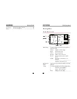
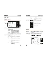
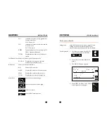
Indicates that a test result is greater than 
the maximum limit.  

PHI= Primary Hi 


PLO 

Indicates that a test result is less than the 
minimum limit.  

PLO = Primary Lo  


SREJ

            The secondary limit is out of range (NG).  

SREJ = Secondary Rejection 


TOTAL


Displays the total amount of failed test 
results. 

Test Results- Pass  Shows the total amount of passed results. 

 Bin1-Bin2 

Displays 

the 

bin range and the total 

amount of passed test results.  

Bin Results 

  Shows the results for each Bin. 


BIN 

Shows the Bin number 


MAX 

X


Displays the maximum limit for each bin 


MIN X 

Displays the minimum limit each bin. 


TOTAL 

Displays the total results for each bin. 

Menu Keys 


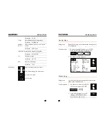
Goes to the next results page. 


Goes to the previous results page. 


Clears the results. 


Exits the Bin Summary menu. 


   LCR-800 

User 

Manual 

70


Bin Summary/Results 


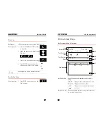
Background 

After the bins have been set up (page 61) and 
sorting has been completed (page 55) the 
measurement results/summary can be shown. 

Panel Operation 

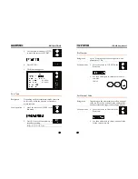
1.


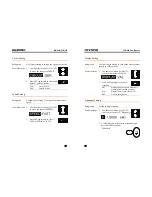
Use the arrow menu keys (F1/F2) 
to move the cursor to BIN SUM. 


2.


Press SET to enter the BIN SUM 
menu. 


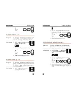
3.


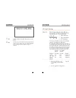
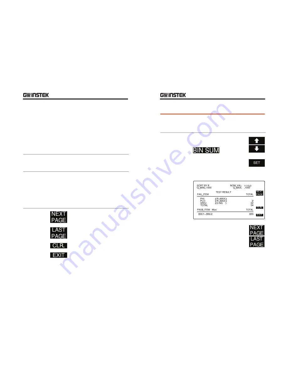
The BIN SUM menu appears 


4.


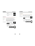
Press NEXT PAGE or LAST PAGE 
to navigate the result pages. 


Summary of Contents for LCR-800 Series

Page 1: ... photocopied reproduced or translated to another language without prior written consent of the Good Will Instrument company The information in this manual was correct at the time of printing However Good Will continues to improve products and reserves the right to change specifications equipment and maintenance procedures at any time without notice Good Will Instrument Co Ltd No 7 1 Jhongsing Rd T...

Page 2: ...0 Parameter Configuration 31 Running Measurement 43 Store Recall 45 BIN FUNCTIONS 48 Binning Menu 50 Set Bin Menu 61 Bin Summary Menu 68 RS232 REMOTE 72 LCR Setup 73 LCR Viewer 74 Terminal Connection 84 PROGRAMMING 87 Command Syntax 87 Commands 90 LCR 800 User Manual 4 INTERACE 111 RS232 Interface Configuration 112 Signal Overview 116 FAQ 121 APPENDIX 123 Fuse Replacement 123 Circuit Theory and Fo...

Page 3: ...ling that leads to damaging the LCR 800 Do not discharge static electricity to the LCR 800 Do not block or obstruct the cooling fan vent opening Do not perform measurement at circuits directly connected to Mains Note below Do not disassemble the LCR 800 unless you are qualified as service personnel Measurement categories EN 61010 1 2001 specifies the measurement categories and their requirements a...

Page 4: ... ionized gases that may produce a reduction of dielectric strength or surface resistivity Pollution degree 1 No pollution or only dry non conductive pollution occurs The pollution has no influence Pollution degree 2 Normally only non conductive pollution occurs Occasionally however a temporary conductivity caused by condensation must be expected Pollution degree 3 Conductive pollution occurs or dr...

Page 5: ...act the supplier This cable appliance should be protected by a suitably rated and approved HBC mains fuse refer to the rating information on the equipment and or user instructions for details As a guide cable of 0 75mm2 should be protected by a 3A or 5A fuse Larger conductors would normally require 13A types depending on the connection method used Any moulded mains connector that requires removal ...

Page 6: ...Intuitive user interface comprehensive measurement functions Interface RS 232C LCR 821 LCR 819 817 816 optional Handler Interface LCR 829 827 826 LCR 800 User Manual 12 Model comparison LCR model Test Frequency 821 819 829 817 827 816 826 12Hz 200kHz 12Hz 100kHz 12Hz 10kHz 100Hz 2kHz Measurement Types Measurement item Primary measurements Capacitance C Inductance L Impedance Z Resistance R Seconda...

Page 7: ...nal or external bias The bias will be displayed on the bottom of the LCD display as INT B internal bias or EXT B external bias 8 On Off The On Off key turns the internal or external bias on or off 4 PPM Measures Dissipation and Quality factor as PPM 1 C V Turns constant voltage mode on or off 0 R H Used to turn Range Hold On or Off FREQ Used to enter test frequencies Numerical numbers Used to ente...

Page 8: ...rrent output Force and Sense terminals Power Switch Turns the power on or off On Off LCR 800 User Manual 16 Rear Panel Overview LCR 819 LCR 817 LCR 816 O_B IN_1 3 O_B IN_1 2 O_BI N_11 O_B IN_1 0 O_B IN_9 O_BI N_8 O_B IN_7 O_BI N_6 O_B IN_5 O_B IN_4 O_BI N_3 O_B IN_2 O_B IN_1 O_P_ OVE R GND VCC GND O_P _HI O_P _LO O_S_ REJ O_IN DEX I_K_ LOC K I_E_ TRIG O_E OM O_S _OV ER LCR 829 LCR 827 LCR 826 LCR ...

Page 9: ...32 Interface RS232 interface LCR 821 RS232 interface is used for remote control with the LCR Viewer software RS232 is also available as a factory installed option LCR 816 817 819 LCR 800 User Manual 18 Power Up Tilt stand Low Angle Ensure the stand is up High Angle Ensure the stand is down Power up Panel operation 1 Connect the power cord to the socket 2 Press the power button The display becomes ...

Page 10: ...scription HFORCE Carries the signal current source Connected to the side of the device under test HSENSE Together with Lsense monitors the Potential Connected to the side of the device under test LSENSE Together with Hsense monitors the Potential Connected to the side of the device under test LFORCE Accepts the signal current return Connected to the side of the device under test GND If the test co...

Page 11: ... and the L side to the negative lead Make sure the distance between the lead base and fixture clip is short enough LCR 800 User Manual 22 H side L side 4 If the test component has an outer case unconnected to either of the leads connect to the ground terminal for noise level reduction External voltage bias connection Background An external voltage bias of 0 30 volts with a maximum of 200mA can be ...

Page 12: ...internal memory of the LCR 800 The Open circuit calibration determines the stray admittance and compensates high impedance measurements The short calibration determines the residual impedance and is used when determining low impedance measurements Open circuit The Open circuit calibration measures the stray admittance of the test fixture This is used for high impedance measurements Procedure 1 Ins...

Page 13: ...ning Failure to pass both tests will result in erroneous measurements LCR 800 User Manual 26 Component Measuring Guidelines Background For measuring Impedance Capacitance Inductance and Resistance series or parallel equivalent circuit models are available Usually a component manufacturer will specify how a component should be measured and at what frequency If not use the guidelines below Select th...

Page 14: ...erminal side If the metal is NOT connected to either of the terminals connect to the GND terminal Wire capacitance When measuring the wire capacitance the fixture clips that are marked with HF High Force HS High Sense should always be connected to the point that is influenced the most by noise LCR 800 User Manual 28 Air cored coils Air cored coils can pick up noise very easily therefore they shoul...

Page 15: ...Q measurements 38 Set constant voltage source 39 Set Range hold 40 Set Average 40 Set Nominal Values 41 Measurement Running Measurement 43 Select Single measurement 43 Select Automatic measurement 44 Store Recall Store Recall 45 Store or Recall Memory Settings 45 Recall Calibration Settings 46 LCR 800 User Manual 30 Measurement Item Description In general two measurement items primary and secondar...

Page 16: ... least 1 Medium 0 2 At least 3 Fast 0 48 At least 7 Panel operation 1 From the main menu press the SPEED menu key to cycle between the various speeds LCR 800 User Manual 32 Displayed measurement unit Measurement units All measurement unit results can be displayed as the absolute values delta values or delta percentage values Value will show the absolute value of the measurement in Ohms Ω Henries H...

Page 17: ...used with both series and parallel equivalent circuits For details about circuit types see the circuit theory chapter on page 124 Measurement type Series Parallel Capacitance C Inductance L Impedance Z Resistance R LCR 800 User Manual 34 Panel operation 1 From the main menu press the CIRCUIT menu key to cycle between the series or parallel equivalent circuits Series Parallel Set Bias voltage Backg...

Page 18: ...5 digit resolution including decimal places Any frequency can be keyed from the number pad and the closest available frequency of 504 will be selected automatically The LCR 818 829 has 503 different frequencies and the LCR 817 827 and LCR 816 826 have 489 and 245 respectively To calculate the different possible frequencies use the tables below LCR 821 Frequency range Formula n range 0 012 To 0 230...

Page 19: ... F5 followed by SETTING F3 and VOLT F2 2 Enter the voltage using the numerical keys and then press ENTER 100mV LCR 800 User Manual 38 1V The voltage is updated in the display If the voltage entered is outside the allowable voltage range the nearest voltage is selected 3 Press F5 EXIT to exit the Setting menu Set PPM for D Q measurements Background Dissipation and Quality Factor D Q measurements ca...

Page 20: ...ual 40 Set Range hold Background When DUTs are disconnected from the test cables fixtures during continuous testing Range Hold can be used to avoid range switching This is particularly useful for repetitively testing a number of DUTs For more information on Range and range hold see the specifications page 136 Panel operation 1 Press 0 R H to turn Range Hold on or off R H ON OFF is toggled each tim...

Page 21: ...e the nominal value set Panel operation 1 From the main menu choose the measuring mode that you wish to change by pressing F3 MODE until the correct measuring mode is displayed For example if L Q mode is selected an inductance mH nominal value can be set LCR 800 User Manual 42 Inductance L H mH Capacitance C nF uF pF Impedance Z Ω KΩ Resistance R Ω KΩ 3 Press MENU F5 followed by SORT F2 and NOM VA...

Page 22: ... and the number of averages used LCR 800 User Manual 44 Select Automatic measurement Background Measurement can be manually controlled MANU or automatically updated AUTO In continuous mode AUTO measurements are automatically done and the display is updated according to the measurement speed setting Panel operation 1 Hold the START key for a few seconds to toggle between automatic AUTO and manual M...

Page 23: ...U SETTING AND MEMORY 2 Press 2 to save the current measurement settings or 1 to recall a previously saved memory setting 2 OR 3 Use the number pad to select a memory number and ENTER to confirm the selection Range 1 100 Memory slot 10 LCR 800 User Manual 46 4 The RECALL NO or STORE NO will be set accordingly RECALL NO VOLTAGE EXIT RECALL 1 AVGE 1 000 VOLT 1 MEMORY AVERAGE RECALL CALIBRATION 10 1 0...

Page 24: ...user defined limits Component sorting can be accomplished in either manual or automatic mode For more information on using the handler interface to sort components please see page 114 Bin Functions Handler Menu Overview 50 Handler Menu 52 Mode Setting 52 Circuit Setting 53 Speed Setting 53 Display Setting 54 Frequency Setting 54 Select Run Auto Manu Sorting 55 Voltage Setting 56 Bias Setting 57 Co...

Page 25: ...in settings MODE Measurement mode SPEED Measurement speed BIN SUM Displays the Bin test results CIRCUIT Selects between serial and parallel circuits DISPLAY Selects what measurement unit is displayed Parameter BIN VALUE OFF Measurement Results The primary and secondary measurement results are displayed Settings The testing settings for the DUT can be edited here F Frequency model dependant V Volta...

Page 26: ...0 User Manual 52 Handler Menu Background Before Bin Sorting the measurement settings must be configured Panel operation 1 To access the handler menu press MENU SORT HANDLER from the main menu 2 The Handler menu appears SLOW V 1 000 RANGE 1 DELAY 00000mS V EXIT SET INT B C V AVG OFF 1 OFF MODE SPEED CIRCUIT DISPLAY BIN SUM VAL SER R Q FAST R 24 83 F 1 0000 Q MANU 0000 kHz Ω SET BIN Mode Setting Bac...

Page 27: ...Press SET repeatedly to select FAST MEDIUM or SLOW LCR 800 User Manual 54 Display Setting Background Use the Display setting to change the measurement results as values or bins Panel Operation 1 Use the arrow menu keys F1 F2 to move the cursor to Display 2 Press SET repeatedly to make a selection VAL Display the primary and secondary measurement results as values BIN Display the bin result BIN1 13...

Page 28: ... To test in MANU mode press the START key for each test Testing will begin automatically in AUTO mode 3 Results will be updated in the display depending on the settings Each time a test result has been completed an asterisk will appear on the screen LCR 800 User Manual 56 Voltage Setting Background Set the testing voltage Panel Operation 1 Use the arrow menu keys F1 F2 to move the cursor to V Volt...

Page 29: ...erent components and component values and to ensure accurate readings Component Inductor Capacitor Resistor Range1 1 16mH f 1 6 25uF f 6 25 100Ω Range2 16 256mH f 100 1600nF f 0 1 1 6kΩ Range3 256 4100mH f 6 4 100nF f 1 6 25 6kΩ Range4 4 1 65H f 400 6400pF f 25 6 410kΩ f test frequency in kHz This range is not used above 20 kHz Panel Operation 1 Use the arrow menu keys F1 F2 to move the cursor to ...

Page 30: ...layed as well This will result in a delay proportional to the Delay Settings Panel Operation 1 Use the arrow menu keys F1 F2 to move the cursor to DELAY 2 Use the number pad to enter the delay time followed by the Enter key 100ms LCR 800 User Manual 60 Average Setting Background The average function chooses how many averages 1 255 are used for each measurement Panel Operation 1 Use the arrow menu ...

Page 31: ...mum bin value as a positive percentage offset from the nominal value Ω Sets the minimum bin value as a negative percentage offset from the nominal value LCR 800 User Manual 62 Q_Max Sets the Maximum Q value for the current bin Q_Min Sets the minimum Q value for the current bin Menu Keys Scroll up through the menu items Scroll down through the menu items Clears the current bin settings Goes to the ...

Page 32: ...ndary sorting R Q C D C R L Q LCR 800 User Manual 64 Bin Number Background Up to 13 sorting bins can be configured with a minimum of 1 bin Panel operation 1 Move the cursor to TOT_BIN in the Bin menu 2 Use the number pad to enter the amount of sort bins 10 bins Set Nominal Value Background Depending on the measurement mode a nominal value can be set The nominal value unit depends on the measuremen...

Page 33: ...of the nominal value The limit units depend on the measurement type see Sort Type page 63 Panel operation 1 Move the cursor to to set the positive percentage limit LCR 800 User Manual 66 2 Use the number pad to enter the maximum percentage value for the current sort bin For example 10 3 Repeat the above procedure for Set Max Min Secondary Measurement Limits Background The absolute maximum and abso...

Page 34: ... Bin1 Exit Set Bin Menu Panel operation 1 Press EXIT at any time to exit the Bin Set menu LCR 800 User Manual 68 Bin Summary Menu Bin Summary Menu Overview Bin Results F1 F5 Ω Ω Ω Bin Parameters Test Results Fail Test Results Pass F2 F4 F5 Bin Parameters Shows the basic bin parameters used for the bin sorting SORT BY Displays what measurement was used NOM_VAL Displays the nominal value _MIN _MAX D...

Page 35: ...r each Bin BIN Shows the Bin number MAX X Displays the maximum limit for each bin MIN X Displays the minimum limit each bin TOTAL Displays the total results for each bin Menu Keys Goes to the next results page Goes to the previous results page Clears the results Exits the Bin Summary menu LCR 800 User Manual 70 Bin Summary Results Background After the bins have been set up page 61 and sorting has ...

Page 36: ... options includes RS232C remote connectivity With the RS232 VIEWER software the LCR meter can be remotely controlled and all test results can be saved to a PC LCR Setup RS232 Settings 73 LCR Viewer LCR VIEWER Display Overview 74 LCR Viewer Connection and File Settings 75 LCR Viewer File Settings 78 LCR Viewer Remote Measurement 80 View Data 81 Terminal Connection Configure Terminal Connection 84 ...

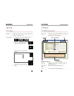
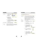
Page 37: ...n the display RS232 INTERFACE EXIT OFF ON ON OFF 4 Press EXIT to return to the main menu LCR 800 User Manual 74 LCR Viewer LCR VIEWER Display Overview Background LCR Viewer mimics the LCR 800 series front panel and operates in a similar manner Message Area Message Display Key Virtual Panel Meter Menu Bar Time Menu Bar Configures all PC settings connection settings and shows data results Virtual Pa...

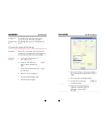
Page 38: ...ction Settings 1 Connect the LCR meter to the PC with an RS232 cable 2 Ensure the LCR 800 is set to manual single measurement mode Page 43 3 Ensure RS232 has been enabled on the LCR meter Page 73 4 Run the LCR Viewer program 5 Go to the Option Settings menu 6 The Settings panel appears LCR 800 User Manual 76 7 Choose the COM port Please see the Windows Device Manager for the applicable COM port se...

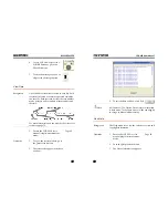
Page 39: ...xtension The file name identifier consists of 4 user defined characters The file number identifier is incremented per 10000 test results If LCR Viewer is terminated before 10000 test results the data will be saved and then the next file will start anew The file number identifier starts at 0001 and increments to a maximum of 9999 The file number identifier cannot be user defined but can be reset to...

Page 40: ...er Remote Measurement Background The LCR Viewer Software mimics the LCR 800 meter front panel Remote operation is identical To operate any of the controls remotely a mouse must be used A keyboard cannot be used Operation of LCR Viewer is the same as the operation of the LCR meter Note If a button is grayed out the key or operation is not currently selectable Operation 1 To choose a menu key click ...

Page 41: ... results see page 78 1 Ensure the LCR 800 is set to manual single measurement mode Page 80 Operation 2 To view the test result data go to the Data result menu 3 The test results appear in the data window LCR 800 User Manual 82 4 To exit the data window click Exit Note All file menus File Option Data Help are restricted in Auto mode To change to manual mode see page 80 to change to Manual mode remo...

Page 42: ...ange to Manual mode remotely LCR 800 User Manual 84 Terminal Connection Configure Terminal Connection Background To connect the LCR 800 to a terminal program follow the instructions below Connection Settings 1 Connect the LCR meter to the PC with an RS232 cable 2 Ensure the LCR 800 is set to manual single measurement mode Page 43 3 Ensure RS232 has been enabled on the LCR meter Page 73 4 Open a te...

Page 43: ...th END M or J M as the terminal characters Terminal command COMU LCR Return COMU ON Terminal command COMU OVER LCR Return COMU OVER 8 The LCR 800 will display RS232 ONLINE when the connection is successful 9 See the Programming chapter for remote programming details Page 87 LCR 800 User Manual 86 Disconnection 10 To disconnect remote control send the following command with END M or J M as the term...

Page 44: ...ally or automatically updated Example MAIN PRIM 32 705 END LCR 800 User Manual 88 Command forms Commands and queries can be written in either ASCII or hexadecimal Below are examples of ASCII and hexadecimal commands ASCII SORT NOMV 32 0000 END M or J M Hex 53 4F 52 54 3A 4E 4F 4D 56 20 2B 33 32 2E 30 30 30 30 0A 0D Command format 1 command header 2 single space 3 parameter 4 message terminator Par...

Page 45: ...N VOLT 1 000 END or J MAIN SPEE FAST END M or J M Hex example 4D 41 49 4E 3A 46 52 45 51 20 31 2E 30 30 30 30 30 0A 4D 41 49 4E 3A 56 4F 4C 54 20 31 2E 30 30 30 0A 4D 41 49 4E 3A 55 50 45 45 3A 46 41 53 54 0A 0D Hex format LCR 800 User Manual 90 Commands SPEED 91 DISPLAY 91 MODE 92 CIRCUIT 93 FREQUENCY 94 VOLTAGE 94 AUTO MANU 95 START 96 RANGE HOLD 96 C V 97 BIAS 97 INT B 98 EXT B 98 PPM 99 OPEN 1...

Page 46: ...played measurement as a value or as an offset from a nominal value Delta or Delta Syntax MAIN DISP string END M or J M Parameter LCR 800 User Manual 92 string Display VALU Unit Value DELP Delta DELT Delta Example MAIN DISP VALU END M Set the display to Value Query Syntax MAIN DISP END M or J M Return String string Display MAIN DISP VALU END Value MAIN DISP DELP END Delta MAIN DISP DELT END Delta Q...

Page 47: ...tring string Equivalent circuit MAIN CIRC SERI END Series LCR 800 User Manual 94 MAIN CIRC PARA END Parallel Query Example MAIN CIRC END M MAIN CIRC PARA END Returns a parallel equivalent circuit as the current setting FREQUENCY Command Query Set or queries the test frequency Syntax MAIN FREQ variable END M or J M Parameter variable Frequency kHz 0 01200 100 000 7 characters including a decimal 12...

Page 48: ... END M or J M Return String string Voltage MAIN TRIG AUTO END MAIN TRIG MANU END Returns automatic mode Returns manual mode Query Example MAIN TRIG END M MAIN TRIG AUTO END LCR 800 User Manual 96 Returns Auto mode as the current measurement mode START Command Starts a measurement in manual mode Syntax MAIN STAR END M or J M Example MAIN STAR END M Starts the measurement RANGE HOLD Command Query Tu...

Page 49: ...IN INTB ON END MAIN INTB OFF END MAIN EXTB ON END MAIN EXTB OFF END Internal Bias is on Internal Bias is off External Bias is on External Bias is off LCR 800 User Manual 98 Query Example MAIN BIAS END M MAIN EXTB ON END Returns the Bias Status External Bias is on INT B Command Query Sets and queries the internal bias Syntax MAIN INTB string END M or J M Parameter String Internal Bias OFF Off ON On...

Page 50: ...100 OPEN Command This command will perform an open circuit calibration A return string will indicate if the calibration was successful or not Syntax OFFS OPEN END M or J M Return String string Open calibration attempt OPEN OK END OPEN FAIL END Successful Failure Example OFFS OPEN END M OPEN OK END Returns the open circuit calibration attempt Successful SHORT Command This command will perform a clo...

Page 51: ...ND M Recalls saved settings from memory slot 100 Query Syntax MEMO NUMB END M or J M Return String LCR 800 User Manual 102 string Memory recall status MEMO NUMB variable END variable 1spsp 100 sp space character OK Returns the memory slot used MEMO RECA EMPT END Not Ok The memory slot is empty therefore no data to recall Query Example MEMO NUMB END M MEMO NUMB 100 END Data was recalled from memory...

Page 52: ...verage number is currently 255 RECALL CALIBRATION Command Recalls the calibration settings from memory A return string indicates if the command was successful Syntax STEP RECA END M or J M Return String string Recall calibration RECA OK END Successful LCR 800 User Manual 104 Example STEP RECA END M or J M RECA OK END Calibration was recalled successfully BAUD RATE Command Sets the baud rate of the...

Page 53: ...ver command is used to resume measurements after the Measure Hold command has been used Syntax COMU RECO END M or J M LCR 800 User Manual 106 Example COMU RECO END M Resume measurement recover measurement LEVEL DISPLAY Command Displays a menu level on the LCR 800 display Returns the menu level Syntax LEVE string END M or J M Parameter string Menu Level MAIN Main display MENU menu display PARA Sett...

Page 54: ...only This measurement is the second measurement displayed after measurements have been started Return Syntax MAIN SECO value unit1 END value Test Result Any 6 digit ASCII character including sp or characters and a decimal point Secondary measurement value LCR 800 User Manual 108 unit1 Primary unit nF pF uF nanofarads picofarads microfarads ksp spsp sp space character kΩ Ω mH Hsp millihenry henry E...

Page 55: ...equivalent circuits with the display set to Value Return Syntax SECO OVER unit1 unit2 END unit1 Primary units nF Pf uF mH Hsp sp space nanofarads picofarads microfarads millihenry henry LCR 800 User Manual 110 unit2 Secondary units k sp kΩ Ω Example SECO OVER nFk END The secondary measurement result exceeds the range kΩ is the secondary unit and nF is the primary unit INITIATION HAS FINISHED Initi...

Page 56: ...R 800 User Manual 112 RS232 Interface Configuration Configure RS 232 interface RS 232 configuration Connector DB 9 Male Baud rate 38400 default Parity None Data bit 8 Stop bit 1 Connect the RS 232 cable to the rear panel port DB 9 male connector Pin assignment 1 2 3 4 5 6 7 8 9 1 DCD Data Carrier Detect 2 RxD Receive Data 3 TxD Transmit Data 4 DTR Data Terminal Ready 5 GND 6 DSR Data Set Ready 7 R...

Page 57: ...8 O _ B I N _ 7 O _ B I N _ 6 O _ B I N _ 5 O _ B I N _ 4 O _ B I N _ 3 O _ B I N _ 2 O _ B I N _ 1 O _ P _ O V E R G N D V C C G N D O _ P _ H I O _ P _ L O O _ S _ R E J O _ I N D E X I _ K _ L O C K I _ E _ T R I G O _ E O M O _ S _ O V E R HANDLER INTERFACE Signal Function Pin1 O_BIN_1 Go Assigned BIN 1 Pin2 O_BIN_2 Go Assigned BIN 2 Pin3 O_BIN_3 Go Assigned BIN 3 Pin4 O_BIN_4 Go Assigned BIN ...

Page 58: ...ler interface Parameter Output Signals O_INDEX The Index signal will become low when the Analog measurement time has completed When the Index signal is low the test component can be replaced with the next component The signal goes high when the next trigger is active O_BIN_1 O_BIN_13 The Bin Go No Go signals go active low when a successful comparison has been made For example if a component is ass...

Page 59: ... 24V 5mA O_S_OVER O_S_REJ O_P_OVER O_P_LO O_P_HI Control Signals O_INDEX O_EOM Pull up resistors R408 R427 must be replaced to output greater than 5V LCR 800 User Manual 118 Parameter Input Signals I_E_TRIG Measurement start signal This signal will trigger the LCR 800 to start a measurement when the signal is pulsed for at least 5us It is triggered by the falling edge of the pulse I_K_LOCK The key...

Page 60: ...r Data Output T3 MIN MAX 5us Calculation and binning time T4 MIN MAX 6ms LCR 800 User Manual 120 Analog Measurement time T5 Slow Medium Fast 0 012kHz 817ms 817ms 817ms 0 1kHz 901ms 125ms 125ms 0 12kHz 901ms 105ms 103ms 1kHz 903ms 59ms 27ms 10kHz 873ms 53ms 17ms 100kHz 873ms 53ms 17ms Trigger Wait Time After O_EOM Output T6 Slow Medium Fast OFF 2ms 2ms 2ms BIN 4ms 4ms 4ms VALUE 16ms 16ms 16ms Binni...

Page 61: ...ort Zeroing can fail The test fixture has an open circuit between the wires and terminal Some functions can impede the short test Ensure Range Hold and Internal External Bias R H and INT B EXT B are disabled See pages 40 39 34 Q3 I cannot see the display clearly A3 Use the display contrast control on the rear panel to adjust the contrast Q4 When using a terminal program I cannot execute a command ...

Page 62: ... diagrams and formulas describing the six types of series and parallel equivalent circuits Capacitive Inductive and Resistive The formulas for all the primary and secondary measurement types are also shown Capacitance C Series diagram Parallel diagram Series formula 2 1 D C C P S D dissipation factor Parallel formula 2 1 D C C S P D dissipation factor Inductance L Series diagram Parallel diagram S...

Page 63: ... between two terminals Conductance is the reciprocal of Resistance and measures how easily the electricity flows Note Conductance is only shown for its relation to Resistance Conductance is not a measurable feature of the LCR 800 series Type Resistance Conductance Series Resistance RS Parallel Resistance RP DC Resistance Rdc Parallel Conductance GP 1 RP Formula jX Z G I V R S 1 C j Z L j Z S S 2 2...

Page 64: ... R L Q S S L R D L j G YP P P L R Q P PG L D LCR 800 User Manual 128 Reactance X and Susceptance B 1 X Formula Background Reactance measures the imaginary part of Impedance Z caused by capacitors or inductors Susceptance is the reciprocal of Reactance and measures the imaginary part of Admittance Y which is the reciprocal of Impedance Note Reactance and Susceptance is only shown for their relation...

Page 65: ...ormula Y I E Z 1 jX R ZS C j R L j R 2 2 X R ZS 2 2 X R RX ZP cos Z RS sin Z XS Z E I Y 1 jB G YP L j G C j G 2 2 B G GB YS 2 2 B G YP cos Y GP sin Y BP LCR 800 User Manual 130 Quality factor Q and Dissipation factor D Formula Background Both Quality factor and its reciprocal Dissipation factor are used for measuring the rate of energy dissipation relative to the measurement frequency Low energy d...

Page 66: ...or Ymin X 1 1 Q 1 Kb Kc Z Ze Depends on whether the component is a capacitor C resistor R or inductor L Circuit Formula for relevant circuit C Ze 2 counts 0 03 0 02 1 Ka or X Ymax or Ymin X 1 D 1 Kb Kc R Ze 2 counts 0 03 0 02 1 Ka or X Ymax or Ymin X 1 Q 1 Kb Kc L Ze 2 counts 0 03 0 02 1 Ka or X Ymax or Ymin X 1 1 Q 1 Kb Kc Secondary Measurement Readout Error Formula D C D 2counts 0 0003 0 0002 1 ...

Page 67: ... constant for Capacitor Min in table 3 4 Rmax Range constant for Resistor Max in table 3 4 Rmin Range constant for Resistor Min in table 3 4 Lmax Range constant for Inductor Max in table 3 4 Lmin Range constant for Inductor Min in table 3 4 Ymax Range constant for either Capacitor Resistor or Inductor Max in table 3 4 Ymin Y range constant for either Capacitor Resistor or Inductor Min in table 3 4...

Page 68: ...al 136 Specifications Specification accuracy is only applicable when the LCR meter has been warmed up for 30 minutes with an operating temperature of 18 C 28 C Measurement Parameters Inductance Ls Lp Capacitance Cs Cp Resistance Rs Rp Dissipation D Quality Factors Q Equivalent Series Resistance ESR and Equivalent Parallel Resistance EPR Impedance Z Phase angle of Impedance degree θ Measurement Mod...

Page 69: ...deviation of the measured L C R or Z value from a saved NOMINAL VALUE The deviation is indicated Delta Delta is similar to the DELTA except that the deviation is shown in suitable units ohms henries etc Measurement Speed Speed LCR 816 817 819 821 LCR 826 827 829 Slow 896ms Please refer to the Handler timing diagram on page 119 for details Medium 286ms Fast 135ms Equivalent circuit Parallel L R L Q...

Page 70: ...er States relating to Electromagnetic Compatibility 2004 108 EC and Low Voltage Equipment Directive 2006 95 EC EMC EN 61326 1 EN 61326 2 1 Electrical equipment for measurement control and laboratory use EMC requirements 2006 Conducted and Radiated Emissions CISPR11 2003 A1 2004 A2 2006 Class A Electrostatic Discharge IEC 61000 4 2 2001 Current Harmonic EN 61000 3 2 2006 Radiated Immunity IEC 61000...

Page 71: ...settings handler menu 54 Dissipation accuracy definition 132 Dissipation factor overview 130 EN61010 measurement category 6 pollution degree 7 Environment operation 7 storage 8 Equivalent circuit model overview 124 Equivalent circuit type 33 Equivalent circuits specification 138 Exit set bin menu 67 External voltage bias connection 22 Features 11 Fixture connection 21 overview 20 Frequency and vol...

Page 72: ... 126 series parallel model 125 Resistance C R L R accuracy definition 132 Results bin summary 70 RS 232 configuration 112 RS232 remote 72 RS232 Settings 73 Run measurement basic measurement 43 Run measurements handler menu 55 Secondary limits set bin menu 66 Secondary measurement accuracy definition 132 Series circuit selection 33 Service contanct point 122 Set Bin menu 62 Set Bin menu overview 61...

Page 73: ...byte with END message NL END or NL J New Line or ASCⅡ Line Feed Character Hex 0A CR M ASCⅡ Carry Return Character Hex 0D CONTENTS z Initialization page 2 Command string page 3 Example page 7 z How to get test result page 13 z Test Result Format page 14 z Continuous Command page 18 z Off Line page 19 ...

Page 74: ...ep 5 If LCR Meter response is COMU OFF END or J M then check below 1 LCR Meter s baud rate set 38400 default so PC have to set the same 2 LCR Meter s RS232 item have to be set on Refer to user manual about OPTION2 in chapter 9 1 3 Please check configuration of cable Refer to user manual about The Configuration of cable in chapter 9 3 5 PC sends command COMU OVER END M or J M 6 Waiting for LCR Mete...

Page 75: ...IN MODE CD END MAIN MODE CR END MAIN MODE LQ END MAIN MODE LR END MAIN MODE ZQ END For Zθ mode 4 CIRCUIT MAIN CIRC SERI END M MAIN CIRC PARA END M MAIN CIRC END M MAIN CIRC SERI END MAIN CIRC PARA END 5 FREQUENCY MAIN FREQ value END M Example MAIN FREQ 0 01200 END M MAIN FREQ END M MAIN FREQ value END Example MAIN FREQ 0 01200 END value 0 01200 100 000 6 VOLTAGE MAIN VOLT value END M Example MAIN ...

Page 76: ... MAIN EXTB END M MAIN EXTB OFF END MAIN EXTB ON END 14 PPM MAIN PPM OFF END M MAIN PPM ON END M MAIN PPM END M MAIN PPM OFF END MAIN PPM ON END 15 OPEN OFFS OPEN END M OPEN OK END OPEN FAIL END 16 SHORT OFFS SHOR END M SHOR OK END SHOR FAIL END 17 NOM VAL SORT NOMV value END M Example SORT NOMV 0 12345 END M SORT NOMV 0 12345 END M SORT NOMV END M SORT NOMV value END Example SORT NOMV 0 12345 END ...

Page 77: ...55 END M SETP AVER END M STEP AVER value END Example STEP AVER 255 END value 1 00 255 21 RECALL CALIBRATION STEP RECA END M RECA OK END 22 BAUDRATE COMU value END M Example COMU 9600 END M COMU value END COMU 9600 END value 9600 19 2 38 4 57 6 1152 23 MODE L NO COMU MONO END M COMU MONO 816 END COMU MONO 817 END COMU MONO 819 END 24 ONLINE COMU END M COMU ON END COMU OFF END 25 MEASURE HOLD COMU H...

Page 78: ...28 Primary Factor MAIN PRIM value END Example MAIN PRIM 32 705 END Test result 29 Secondary Factor Unit for R Q C D L Q MAIN SECO value unit1 END Example MAIN SECO 0045nF END Test result Unit1 for Primary Factor 30 Secondary Factor Unit for C R MAIN SECO value unit1 unit2 END Example MAIN SECO 0045nFk END Test result Unit1 for Primary Factor Unit2 for Secondary Factor 31 Initiation has finished CO...

Page 79: ...r Response COMU OVER END ASCII CODE 43 4F 4D 55 3A 4F 56 45 52 0A Hex format Set Speed PC send command MAIN SPEE FAST END M or J M ASCII CODE 4D 41 49 4E 3A 55 50 45 45 3A 46 41 53 54 0A 0D Hex format LCR Meter Response MAIN SPEE FAST END ASCII CODE 4D 41 49 4E 3A 53 50 45 45 3A 46 41 53 54 0A Hex format Set Frequency PC send command MAIN FREQ 1 00000 END M or J M ASCII CODE 4D 41 49 4E 3A 46 52 4...

Page 80: ...V 32 0000 END ASCII CODE 53 4F 52 54 3A 4E 4F 4D 56 20 2D 33 32 2E 30 30 30 30 0A Hex format Set Voltage PC send command MAIN VOLT 1 000 END M or J M ASCII CODE 4D 41 49 4E 3A 56 4F 4C 54 20 31 2E 30 30 30 0A 0D Hex format LCR Meter Response MAIN VOLT 1 000 END ASCII CODE 4D 41 49 4E 3A 56 4F 4C 54 20 31 2E 30 30 30 0A Hex format Set Average PC send command STEP AVER 1 00 END M or J M ASCII CODE 5...

Page 81: ...E 55 4D 42 20 31 20 20 0A Hex format Test Result for Primary Factory LCR Meter Response MAIN PRIM 32 705 END ASCII CODE 4D 41 49 4E 3A 50 52 49 4D 20 20 33 32 2E 37 30 35 0A Hex format Test Result f or Secondary Factory and Unit 1 R Q C D L Q Display VALUE DELTA LCR Meter Response MAIN SECO 0045nF END ASCII CODE 4D 41 49 4E 3A 53 45 43 4F 20 20 2E 30 30 34 35 6E 46 0A Hex format 2 C R Display VALU...

Page 82: ...5 3A 4F 46 46 2E 0A Hex format Set Manual mode PC send command MAIN TRIG MANU END M or J M ASCII CODE 4D 41 49 4E 3A 54 52 49 47 3A 4D 41 4E 55 0A 0D Hex format LCR Meter Response MAIN TRIG MANU END ASCII CODE 4D 41 49 4E 3A 54 52 49 47 3A 4D 41 4E 55 0A Hex format Set BAUDRATE EX change to 115200 PC send command COMU 1152 END M or J M ASCII CODE 43 4F 4D 55 3A 31 31 35 32 0A 0D Hex format LCR Met...

Page 83: ...ODE 4C 45 56 45 3A 4F 46 46 53 0A Hex format Step2 PC send command OFFS OPEN END M or J M ASCII CODE 4F 46 46 53 3A 4F 50 45 4E 0A 0D Hex format When open test is ok LCR Meter Response OPEN OK END ASCII CODE 4F 50 45 4E 3A 4F 4B 0A Hex format When open test is fail LCR Meter Response OPEN FAIL END ASCII CODE 4F 50 45 4E 3A 46 41 49 4C 0A Hex format ...

Page 84: ...DE 4C 45 56 45 3A 4F 46 46 53 0A Hex format Step2 PC send command OFFS SHOR END M or J M ASCII CODE 4F 46 46 53 3A 53 48 4F 52 0A 0D Hex format When short test is ok LCR Meter Response SHOR OK END ASCII CODE 53 48 4F 52 3A 4F 4B 0A Hex format When short test is fail LCR Meter Response SHOR FAIL END ASCII CODE 53 48 4F 52 3A 46 41 49 4C 0A Hex format ...

Page 85: ...d any command 2 Trigger mode is selected to MANU mode If the MANU mode is selected LCR Meter doesn t process the measurement and send test result to pc automatically PC have to send a command of MAIN STAR END M or J M to LCR Meter If test frequency at 1kHz and test speed at slow PC have to wait 800ms at least Then LCR Meter will sequent send 2 command for test result Note Test result format refer ...

Page 86: ...ctor and primary s unit LCR Meter response MAIN SECO 0045nF END ASCII CODE 4D 41 49 4E 3A 53 45 43 4F 20 20 2E 30 30 34 35 6E 46 0A Hex format Positive symbol Primary factor unit Ex When R 1ohm Q 0005 R Q mode and display mode is VALUE 1 Primary factor of test result It doesn t include primary s unit LCR Meter response MAIN PRIM 1 0000 END ASCII CODE 4D 41 49 4E 3A 50 52 49 4D 20 20 31 2E 30 30 30...

Page 87: ...1 49 4E 3A 53 45 43 4F 20 20 2E 30 30 30 35 6B 20 0A Hex format Positive symbol Primary factor s unit Ex When R 1kohm Q 0005 R Q mode and display mode is VALUE 1 Primary factor of test result It doesn t includes primary s unit LCR Meter response MAIN PRIM 1 0000 END ASCII CODE 4D 41 49 4E 3A 50 52 49 4D 20 2D 31 2E 30 30 30 30 0A Hex format Negative symbol 2 Secondary factor and unit LCR Meter res...

Page 88: ...it ASCII CODE 4D 41 49 4E 3A 53 45 43 4F 20 20 2E 30 30 34 35 6E 46 6B 0A Hex format Positive symbol Primary factor s unit Ex When C 1nF R 0045 ohm C R mode and display mode is VALUE 1 Primary factor of test result It doesn t include Primary s unit LCR Meter response MAIN PRIM 1 0000 END ASCII CODE 4D 41 49 4E 3A 50 52 49 4D 20 20 31 2E 30 30 30 30 0A Hex format Positive symbol 2 Secondary factor ...

Page 89: ...dary factor s unit Ex When C 00001nF R OVER kohm C R mode and display mode is VALUE 1 Primary factor of test result It doesn t include Primary s unit LCR Meter response MAIN PRIM 00001 END ASCII CODE 4D 41 49 4E 3A 50 52 49 4D 20 20 2E 30 30 30 30 31 0A Hex format Positive symbol 2 Secondary factor and unit LCR Meter response SECO OVER nFk END Secondary factor s unit ASCII CODE 53 45 43 4F 3A 4F 5...

Page 90: ...fer to below NL END or J New Line or ASCⅡ Line Feed Character Hex 0A CR M ASCⅡ Carry Return Character Hex 0D Example Setting Frequency Voltage and Test Speed PC send command MAIN FREQ 1 00000 END or J MAIN VOLT 1 000 END or J MAIN SPEE FAST END M or J M ASCII CODE 4D 41 49 4E 3A 46 52 45 51 20 31 2E 30 30 30 30 30 0A 4D 41 49 4E 3A 56 4F 4C 54 20 31 2E 30 30 30 0A 4D 41 49 4E 3A 55 50 45 45 3A 46 ...

Page 91: ...to LCR Meter LCR Meter will respond a command COMU OFF END to PC and recover display after receive PC command Command String PC sends command COMU OFF END M or J M ASCII CODE 43 4F 4D 55 3A 4F 46 46 2E 0A 0D Hex format LCR Meter response COMU OFF END ASCII CODE 43 4F 4D 55 3A 4F 46 46 2E 0A Hex format ...

Reviews: