3.
Menu/Select
▲
Pressing this button pops up the OSD menus on the screen, and used to
select (“Up” direction) the OSD control options on the screen.
4.
Menu/Select
▼
Pressing this button pops up the OSD menus on the screen, and used to
select (“Down” direction) the OSD control options on the screen.
5.
+
This button is used to increase the value of the selected OSD control option.
6.
−
(1) This button is used to adjust the decreasing value of the selected OSD control
option. (2) used to select input sources (VGA or Video signal) when the OSD “main
menu” function is off (for model with video-in function only).
7.
MSR (Magnetic Strip Reader) Holder
(optional module)
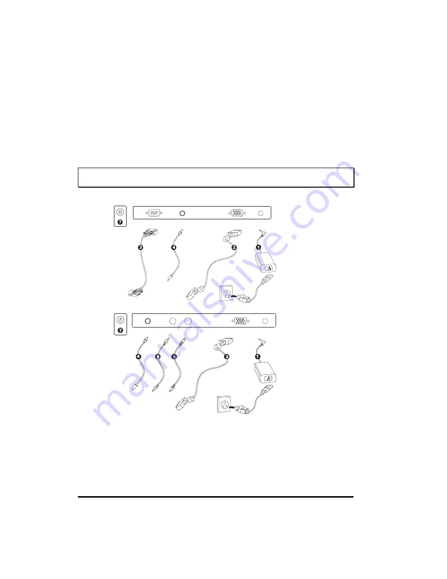
Setting Up
WARNING
When you disconnect the cord/cables, be sure to hold the connector instead
of the wire part.
Touch Screen Model:
Analog/Video-in Model:
1. Connect one end of the
power adapter
to the monitor and the other end to the connector
of the power cord. ( )
2. Connect one end of the
signal cable
to the rear side of computer and the other to the LCD
monitor. Tighten by turning clockwise the two thumb screws to ensure proper grounding.
( )
3. Connect one end of the
touch (RS232
)
cable
to the rear side of computer and the other to
the LCD monitor. Tighten by turning clockwise the two thumb screws to ensure proper
grounding. ( ) (optional module)
4


