background image

Configuration

G&D DP-Vision-IP · 

24

English

The basic operation of the on-screen display (see page 24) and the web application 

Config Panel

 (see page 26) is described on the following pages.

Operating the on-screen display at the console

The on-screen display (OSD) – just like the web application 

Config Panel

, which is 

described on the following – can be used to change the configuration of the KVM 

extender.

The on-screen display can be opened by pressing a configured hotkey at the user 

module. You can view and edit the settings of the KVM extender only in the 

remote 

OSD

 of the 

computer module

.

Showing the on-screen display at the console

How to open the on-screen display:

1. Press 

Ctrl+Num

 (standard) to open the on-screen display.

Layout of the on-screen display

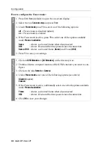
After pressing the hotkeys, the OSD is displayed on the console monitor:

The on-screen display consists of three parts:

Function

Default setting

Page

Changing the colour of the information display

light green

49

Information display

temporary

50

Adjusting the transparency of the on-screen display

average transparency

51

Changing the position of the information dispaly

left upper corner

52

Changing the position of the on-screen display

centred

52

NOTE: 

Use the 

remote hotkey

 (default: 

Ctrl

+

Num

) at the console to open and config-

ure the remote OSD of the computer module and the 

local hotkey

 (default: 

Alt

+

Num

to open and configure the local OSD of the user module.
During the starting process of the user module, the settings of both hotkeys are 

shown (see 

Starting process

 on page 10).

Configuration
Console setup

...

Local console setup

...

Target setup

...

System setup

...

Network setup

...

Information

...

Target power

turn off

ESC


Summary of Contents for DP-Vision-IP

Page 1: ...Guntermann Drunck GmbH www gdsys de G D DP Vision IP AA9100303 1 00 Installation und Bedienung DE EN Installation and Operation ...

Page 2: ... G D übernimmt keine Gewährleistung für Geräte die nicht bestimmungsgemäß eingesetzt wurden nicht autorisiert repariert oder modifiziert wurden schwere äußere Beschädigungen aufweisen welche nicht bei Lieferungserhalt angezeigt wurden durch Fremdzubehör beschädigt wurden G D haftet nicht für Folgeschäden jeglicher Art die möglicherweise durch den Einsatz der Produkte entstehen können Warenzeichenn...

Page 3: ...s for a Class A dig ital device pursuant to Part 15 of the FCC Rules These limits are designed to provide reasonable protection against harmful inter ference when the equipment is operated in a commercial environment This equipment generates uses and can radiate radio frequency energy and if not installed and used in accordance with the instruction manual may cause harmful interference to radio co...

Page 4: ...latzmoduls konfigurieren 15 Konfiguration der Netzwerkschnittstelle 15 Konfiguration der globalen Netzwerkeinstellungen 15 Konfiguration der KVM over IP Verbindung 16 Anschluss der Module an das Produktivnetzwerk 17 Erweiterte Einstellungen der KVM over IP Verbindung 17 Bandbreite limitieren 17 Klassifizierung der IP Pakete DiffServ 17 Signale de aktivieren 18 Bedienung 19 Konkurrierende Bedienung...

Page 5: ... Änderung des Scancode Sets einer PS 2 Tastatur 43 Tastatur für Start des Arbeitsplatzmoduls erforderlich 45 Wartezeit des Bildschirmschoners einstellen 46 Tastaturlayout für Eingaben innerhalb des OSDs auswählen 47 Wiederherstellung der Standardeinstellungen 48 Farbe der Informationseinblendung ändern 49 Anzeige der Informationseinblendung 50 Transparenz des On Screen Displays einstellen 51 Posit...

Page 6: ...ngsversorgung am Gerät ab Ständigen Zugang zu den Netzsteckern der Geräte sicherstellen Achten Sie bei der Installation der Geräte darauf dass die Netzstecker der Geräte jederzeit zugänglich bleiben Lüftungsöffnungen nicht verdecken Bei Gerätevarianten mit Lüftungsöffnungen ist eine Verdeckung der Lüftungs öffnungen unbedingt zu vermeiden Korrekte Einbaulage bei Geräten mit Lüftungsöffnungen siche...

Page 7: ...ng zwischen dem Rechner und dem Arbeitsplatzmodul erfolgt komprimiert und verschlüsselt AES 128 mittels G Ds KVM over IP Technologie über das Gigabit Ethernet Layer 3 Bei ausreichend nutzbarer Bandbreite des Gigabit Ethernets wird das Videosignal mit verlustfreier Videoqualität und nahezu latenzfrei wiedergegeben Mittels manu ellem Bandbreiten Management können Sie die Übertragung an unterschiedli...

Page 8: ...CON Zusätzlich befindet sich folgendes Zubehör im Lieferumfang der Geräte 2 Stromversorgungskabel PowerCable 2 Standard 1 Videokabel DP Cable M M 2 1 USB Gerätekabel USB AM BM 2 2 Audio Kabel Audio M M 2 1 serielles Anschlusskabel RS232 M F 2 1 Servicekabel USB Service 2 1 Installations und Bedienhandbuch 1 Bedienhandbuch für Webapplikation Config Panel ...

Page 9: ...n IP CON in der Nähe des entfern ten Arbeitsplatzes 4 Entnehmen Sie die mitgelieferten Kabel der Verpackung und legen Sie diese für die Installation der Geräte bereit WICHTIG Stellen Sie bei der Standortwahl der Geräte sicher dass die zulässige Umgebungstemperatur siehe Technische Daten auf Seite 57 in der unmittelbaren Nähe eingehalten und nicht durch andere Geräte beeinflusst wird HINWEIS Die ma...

Page 10: ...yb CPU Verbinden Sie die PS 2 Tastatur Schnittstelle des Rechners mit dieser Schnittstelle Verwenden Sie hierzu ein separat erhältliches PS 2 Kabel PS 2 M M 2 Mouse CPU Verbinden Sie die PS 2 Maus Schnittstelle des Rechners mit dieser Schnitt stelle Verwenden Sie hierzu ein separat erhältliches PS 2 Kabel PS 2 M M 2 WICHTIG Verbinden Sie das Rechnermodul für die Ersteinrichtung mittels einer direk...

Page 11: ...erwenden Sie hierzu ein Audio Anschlusskabel Audio M M 2 RS232 Verbinden Sie eine 9 polige serielle Schnittstelle des Rechners mit dieser Schnittstelle Verwenden Sie hierzu das Kabel RS232 M F 2 HINWEIS Die Audio Daten werden in der Standardeinstellung des KVM Exten ders zwischen den Switches übertragen Zusätzlich können Sie im OSD die Übertragung der RS232 Daten aktivieren und alternativ die Über...

Page 12: ...hse können Sie ein optionales Tischnetzteil anschließen Hierdurch wird eine zweite redundante Stromversorgung des Gerätes erreicht HINWEIS Die Tastatur des lokalen Arbeitsplatzes können Sie wahlweise als PS 2 oder USB Gerät anschließen TIPP Verwenden Sie den Adapter MD6M 2xMD6F A6400043 zum gleichzeitigen Anschluss einer PS 2 Tastatur und einer PS 2 Maus Keyb Mouse Network Main Power Keyb CPU RS23...

Page 13: ... anschließen Aktivieren Sie den Generic HID Modus siehe USB HID Modus auswählen auf Seite 40 wenn Sie ein anderes USB Eingabegerät anschließen möchten Die Daten des USB Ein gabegerätes werden in diesem Modus unverändert an das Rechnermodul übertragen Keyb Schließen Sie die PS 2 Tastatur des Arbeitsplatzes an Mouse Schließen Sie die PS 2 Maus des Arbeitsplatzes an HINWEIS Verbinden Sie das Rechnerm...

Page 14: ... ein Red Power Stecken Sie ein mitgeliefertes Kaltgerätekabel ein Hierdurch wird eine zweite redundante Stromversorgung des Arbeitsplatzmoduls erreicht HINWEIS Die Audio Daten werden in der Standardeinstellung des KVM Exten ders zwischen den Switches übertragen Zusätzlich können Sie im OSD die Übertragung der RS232 Daten aktivieren und alternativ die Übertragung der Audio Daten deaktivieren siehe ...

Page 15: ...en ab Seite 56 On Screen Display des Arbeitsplatzmoduls Beim Start des Arbeitsplatzmoduls werden Informationen über den Startvorgang sowie die Firmware Versionen und ID Nummern der verbundenen Module auf dem Monitor des Arbeitsplatzes angezeigt Zusätzlich werden der Local hotkey Standard Alt Num zum Öffnen des lokalen OSD des Arbeitsplatzmoduls und der Remote hotkey Standard Strg Num zum Öffnen de...

Page 16: ...einem Arbeitsplatzmodul Über das OSD können Sie die Konfiguration beider Module nach der Inbetriebnahme anpassen Die IP Adressen und die KVM over IP Einstellungen sind wie folgt vorkonfiguriert WICHTIG Ändern Sie die voreingestellten IP Adressen bevor Sie mehrere Rech ner bzw Arbeitsplatzmodule in das Produktivnetzwerk integrieren TIPP Falls Ihnen die IP Adresse eines bereits konfigurierten Arbeit...

Page 17: ...ation Port 18245 Local Data Port 18244 Remote Host 172 17 0 10 Remote Control Port 18246 HINWEIS Für den Aufbau der KVM over IP Verbindung durch das Arbeitsplatzmo dul sind die Angabe der IP Adresse des Rechnermoduls Host sowie die Angabe des Control Ports des Rechnermoduls erforderlich Die Konfiguration der Communication Ports und Data Ports werden automatisch zwi schen beiden Modulen ausgetausch...

Page 18: ...ngen stellen auch in komplexen Netzwerken sicher dass der KVM Extender aus allen Teilnetzwerken erreichbar ist So konfigurieren Sie die globalen Netzwerkeinstellungen 1 Verwenden Sie den Remote Hotkey Strg Num zum Aufruf des Rechnermodul OSD 2 Wählen Sie die Zeile Network setup und betätigen Sie die Eingabetaste 3 Wählen Sie die Zeile Interfaces und betätigen Sie die Eingabetaste Operational mode ...

Page 19: ...tting folgende Daten 4 Betätigen Sie die F2 Taste zur Speicherung der durchgeführten Änderungen Global preferences Betätigen Sie die F8 Taste zur Auswahl des Betriebsmodus Static Verwendung von statischen Einstellungen DHCP Bezug der Einstellungen von einem DHCP Server Hostname Geben Sie den Host Namen des Gerätes ein Domain Geben Sie die Domäne an welcher das Gerät angehören soll Gateway Geben Si...

Page 20: ...chbar ist So konfigurieren Sie die globalen Netzwerkeinstellungen 1 Verwenden Sie den Local Hotkey Alt Num zum Aufruf des Arbeitsplatzmodul OSD 2 Wählen Sie die Zeile Network setup und betätigen Sie die Eingabetaste 3 Wählen Sie die Zeile Interfaces und betätigen Sie die Eingabetaste HINWEIS Sie können am Arbeitsplatz mit dem Local Hotkey Standard Alt Num das lokale OSD des Arbeitsplatzmoduls und ...

Page 21: ...e zur Speicherung der durchgeführten Änderungen Global preferences Betätigen Sie die F8 Taste zur Auswahl des Betriebsmodus Static Verwendung von statischen Einstellungen DHCP Bezug der Einstellungen von einem DHCP Server Hostname Geben Sie den Host Namen des Gerätes ein Domain Geben Sie die Domäne an welcher das Gerät angehören soll Gateway Geben Sie die IP Adresse des Gateways an DNS 1 Geben Sie...

Page 22: ...hlen Sie die Zeile KVM connection und betätigen Sie die Eingabetaste 3 Geben Sie in der Zeile Bandwidth limit Mb s das Bandbreiten Limit in Mb s für die KVM over IP Verbindung ein 4 Betätigen Sie die F2 Taste zur Speicherung der durchgeführten Änderungen Klassifizierung der IP Pakete DiffServ Für QoS Zwecke Quality of Service deutsch Dienstgüte haben Sie die Möglich keit Differentiated Services Co...

Page 23: ...ertragung des Audio bzw RS232 Signals 1 Verwenden Sie den Remote Hotkey Strg Num zum Aufruf des Rechnermodul OSD 2 Wählen Sie die Zeile KVM connection und betätigen Sie die Eingabetaste 3 Wählen Sie in der Zeile Activated signals das Kontrollkästchen des zu de aktivie renden Signals mit den Pfeiltasten aus und betätigen Sie die F8 Taste 4 Betätigen Sie die F2 Taste zur Speicherung der durchgeführt...

Page 24: ... Rechners wie der an beiden Arbeitsplätzen freigeschaltet Alternativ zur konkurrierenden Bedienung des Rechners durch die Arbeitsplätze kann die exklusive Bedienung s Seite 19 aktiviert werden Verwandte Themen Änderung der Zeitspanne der Eingabesperre auf Seite 32 Änderung der Videobetriebsart der Arbeitsplätze auf Seite 34 Exklusive Bedienung des KVM Extenders Um die exklusive Bedienung des KVM E...

Page 25: ...aste um die in der Zeile angezeigt Operation auszuführen turn off Steckdose n ausschalten turn on Steckdose n einschalten HINWEIS Nach Aktivierung der exklusiven Bedienung des KVM Extenders an einem Arbeitsplatz blinken an der Tastatur des gesperrten Arbeitsplatzes abwech selnd die Caps Lock und die Num sowie Scroll Lock LEDs Die exklusive Bedienung des KVM Extenders wird am aktiven Arbeitsplatz d...

Page 26: ...s und halten Sie diesen gedrückt 3 Halten Sie den Taster weiterhin gedrückt und schalten Sie das Gerät ein 4 Sobald die grüne System LED schnell blinkt lassen Sie die Taste los HINWEIS Um die versehentliche Betätigung des Tasters zu vermeiden ist dieser hinter einer Bohrung in der Frontblende platziert Verwenden Sie einen dünnen und spitzen Gegenstand zur Betätigung des Tasters HINWEIS Führen Sie ...

Page 27: ...rregeln den Zugang auf die Webappli kation können Sie die Netzfilterregeln temporär deaktivieren um diese anschlie ßend zu editieren So deaktivieren Sie die eingerichteten Netzfilterregeln temporär 1 Schalten Sie das Gerät ein falls dieses derzeit ausgeschaltet ist und warten Sie bis es betriebsbereit ist 2 Betätigen Sie den Reset Taster auf der Frontseite des Gerätes und halten Sie diesen 5 Sekun...

Page 28: ...läuterungen der Funktionen aufgeführt Funktion Standardeinstellung Seite Änderung des Hotkeys Strg 28 Änderung der OSD Taste Num 29 On Screen Display mit doppeltem Tastendruck starten ausgeschatet 30 Änderung der Exklusiv Taste Druck 31 Änderung der Zeitspanne der Eingabesperre 1 Sekunde 32 Berechtigung für exklusiven Zugriff des Arbeitsplatzes erteilt 33 Änderung der Videobetriebsart der Arbeitsp...

Page 29: ...rd Aufbau des On Screen Displays Nach der Ausführung des Hotkeys wird das OSD auf dem Monitor des Arbeitsplat zes angezeigt Die Menüansichten des On Screen Displays bestehen aus drei Hauptbereichen Funktion Standardeinstellung Seite Farbe der Informationseinblendung ändern hellgrün 49 Anzeige der Informationseinblendung temporär 50 Transparenz des On Screen Displays einstellen mittleres Durchschei...

Page 30: ...ormationen aufge führt Pfeiltasten Mit den Pfeiltasten Hoch und Runter in einigen Menüs auch Links und Rechts bewegen Sie die Positionsmarke zwischen verschiedenen Menüeinträgen Eingabetaste Diese Taste wird zur Bestätigung von Eingaben oder zum Aufruf eines Untermenüs verwendet Esc Diese Taste schließt die aktuell angezeigte Menüansicht und zeigt das übergeordnete Menü an Falls Eingaben geändert ...

Page 31: ...Java Anwendung unabhängig von den Einstellungen und der Java Kompatibilität des Webbrowsers Start der Webapplikation So starten Sie die Webapplikation Config Panel 1 Geben in der Adresszeile folgende URL ein https IP Adresse des Rechner oder Arbeitsplatzmoduls 2 Klicken Sie auf Download Config Panel HINWEIS Grundlegende Informationen zu den Systemvoraussetzungen der erfor derlichen Konfiguration d...

Page 32: ...tzernamen ein Passwort Geben Sie das Passwort Ihres Benutzerkontos ein Sprachauswahl Wählen Sie die Sprache der Benutzeroberfläche Default Standardeinstellung anwenden English Deutsch WICHTIG Ändern Sie das voreingestellte Passwort des Administratorkontos Melden Sie sich hierfür mit dem Administratorkonto in die Webapplikation ein und ändern Sie anschließend das Passwort wie im separaten Handbuch ...

Page 33: ...Sie die Eingabetaste 3 Wählen Sie die Zeile Hotkey und betätigen Sie die Eingabetaste 4 Wählen Sie im Abschnitt Modifier mindestens eine der aufgeführten Hotkey Modifizierertasten durch Markierung des entsprechenden Kontrollkäst chens mit den Pfeiltasten und anschließende Betätigung der F8 Taste aus Ctrl Strg Taste Standard Alt Alt Taste Alt Gr Alt Gr Taste Win Windows Taste Shift Umschalttaste 5 ...

Page 34: ...y durch Betätigung der F8 Taste eine OSD Taste aus welche gemeinsam mit der bzw den Hotkey Modifizierertaste n den Aufruf des On Screen Displays bewirkt Num Num Taste Standard Pause Pause Taste Insert Einfg Taste Delete Entf Taste Home Pos 1 Taste End Ende Taste PgUp Bild Taste PgDn Bild Taste Space Leertaste 5 Betätigen Sie die F2 Taste zur Speicherung der durchgeführten Änderungen Config Panel 1...

Page 35: ... Taste Alt Gr OSD Aufruf mit doppeltem Druck auf die Alt Gr Taste Win OSD Aufruf mit doppeltem Druck auf die Windows Taste Shift OSD Aufruf mit doppeltem Druck auf die Umschalt Taste Print OSD Aufruf mit doppeltem Druck auf die Druck Taste 5 Betätigen Sie die F2 Taste zur Speicherung der durchgeführten Änderungen Config Panel 1 Klicken Sie im Strukturbaum auf KVM Extender Alle Extender 2 Doppelkli...

Page 36: ...On Screen Display mit dem Hotkey Strg Num Standard 2 Wählen Sie die Zeile System setup und betätigen Sie die Eingabetaste 3 Wählen Sie die Zeile Hotkey und betätigen Sie die Eingabetaste 4 Wählen Sie in der Zeile Exclusive key durch Betätigung der F8 Taste die Exklusiv Taste aus Backspace Rückschritt Taste Print Druck Taste Standard Scroll Rollen Taste Num Num Taste Pause Pause Taste Insert Einfg ...

Page 37: ... 90 Sekunden eingestellt werden So ändern Sie die Zeitspanne der Eingabesperre Verwandtes Thema Exklusive Bedienung des KVM Extenders auf Seite 19 OSD 1 Starten Sie das On Screen Display mit dem Hotkey Strg Num Standard 2 Wählen Sie die Zeile System setup und betätigen Sie die Eingabetaste 3 Geben Sie im Feld Multiuser input lock die gewünschte Zeitspanne der Eingabesperre 1 bis 90 Sekunden ein 4 ...

Page 38: ...Sie die Berechtigung für exklusiven Zugriff eines Arbeitsplatzes HINWEIS Nach Aktivierung der exklusiven Bedienung des KVM Extenders an einem Arbeitsplatz blinken an der Tastatur des gesperrten Arbeitsplatzes abwech selnd die Caps Lock und die Num sowie Scroll Lock LEDs Die exklusive Bedienung des KVM Extenders wird am aktiven Arbeitsplatz durch das Blinken der Scroll Lock LED angezeigt OSD 1 Star...

Page 39: ...eren Arbeitsplatz wird angezeigt sobald die Eingaben des Anwenders am Arbeitsplatz abgeschlossen sind Config Panel 1 Klicken Sie im Strukturbaum auf KVM Extender Alle Extender 2 Doppelklicken Sie das Rechnermodul des zu konfigurierenden KVM Extenders 3 Klicken Sie auf den Reiter Lokal falls Sie die Berechtigung für den lokalen Arbeitsplatz am CPU Modul einstellen möchten Klicken Sie auf den Reiter...

Page 40: ...in der Zeile Video mode durch Betätigung der F8 Taste zwischen folgenden Optionen always on Bild immer an Standard switch off Bild bei Aktionen am anderen Arbeitsplatz ausschalten 4 Betätigen Sie die F2 Taste zur Speicherung der durchgeführten Änderungen Config Panel 1 Klicken Sie im Strukturbaum auf KVM Extender Alle Extender 2 Doppelklicken Sie das Rechnermodul des zu konfigurierenden KVM Extend...

Page 41: ...rden Ausführliche Informationen hierzu finden Sie im separaten Handbuch zur Webapplikation Config Panel So wählen Sie den EDID Modus des KVM Extenders HINWEIS Beachten Sie bei der Erstinbetriebnahme sowie bei Anschluss eines anderen Monitors die auf Seite 10 empfohlene Einschaltreihenfolge OSD 1 Starten Sie das On Screen Display mit dem Hotkey Strg Num Standard 2 Wählen Sie die Zeile Target setup ...

Page 42: ...odul des zu konfigurierenden KVM Extenders 3 Klicken Sie auf den Reiter Allgemein 4 Wählen Sie im Feld Edid Profil zwischen folgenden Optionen Auto automatische Behandlung der EDID Daten Standard GUD DVI von G D erstelltes Profil für eine bestimmte Auflösung Name vom Benutzer eingelesenes EDID Profil 5 Klicken Sie auf OK um die erfassten Daten zu speichern HINWEIS Abhängig vom Bildinhalt können ge...

Page 43: ...en KVM Extenders 3 Klicken Sie auf den Reiter Allgemein 4 Wählen Sie im Feld Farbtiefe zwischen folgenden Optionen 24 bit Übertragung der Bilddaten mit einer maximalen Farbtiefe von 24 bit Standard 18 bit Reduzierung der Farbtiefe der Bilddaten auf 18 bit 5 Klicken Sie auf OK um die erfassten Daten zu speichern OSD 1 Starten Sie das On Screen Display mit dem Hotkey Strg Num Standard 2 Wählen Sie d...

Page 44: ...ein 4 Wählen Sie im Feld Freeze Modus zwischen folgenden Optionen s oben Deaktiviert Standard Aktiviert 5 Falls der Freeze Modus aktiviert ist wählen Sie zusätzlich eine oder beide Optionen im Feld Freeze Visualisierung Rahmen Anzeige eines farbigen Rahmens bei Verbindungsabbruch OSD Einblendung des Hinweises Frozen und der vergangenen Zeit seit dem Verbindungsabbruch 6 Klicken Sie auf OK um die e...

Page 45: ...nd Tablets Sie können den am KVM Extender angeschlossenen Rechner mit einem der unterstützten Displays oder Tablets bedienen WICHTIG Der Generic HID Modus unterstützt viele der am Markt erhältlichen HID Geräte Der Betrieb eines bestimmten HID Gerätes im Generic HID Modus kann nicht gewährleistet werden WICHTIG Bei Anschluss eines USB Hubs oder USB Verbundgerätes mit mehre ren USB Geräten kann nur ...

Page 46: ...e Tastatur anschließen Die Anordnung der 108 Tasten solcher Tastaturen ent spricht dem OpenVMS Tastaturlayout Ein spezieller USB Tastaturmodus gewährleistet die Übermittlung der Betätigung einer Sondertaste dieser Tastatur an den Zielrechner Wacom Intuos4 XL Wacom Int 4XL Wacom Intuos5 S Wacom Int 5S Wacom Intuos5 M Wacom Int 5M Wacom Intuos5 L Wacom Int 5L EINGABEGERÄT EINSTELLUNG beliebiges USB ...

Page 47: ...l des zu konfigurierenden KVM Extenders 3 Klicken Sie auf den Reiter Allgemein 4 Wählen Sie im Feld USB HID Mode die gewünschte Option s oben 5 Klicken Sie auf OK um die erfassten Daten zu speichern OSD 1 Starten Sie das On Screen Display mit dem Hotkey Strg Num Standard 2 Wählen Sie die Zeile Console setup und betätigen Sie die Eingabetaste falls Sie die Unterstützung einer Spezialtastatur für de...

Page 48: ...Set 3 empfehlenswert Config Panel 1 Klicken Sie im Strukturbaum auf KVM Extender Alle Extender 2 Doppelklicken Sie das Rechnermodul des zu konfigurierenden KVM Extenders 3 Klicken Sie auf den Reiter Lokal falls Sie die Unterstützung einer Spezialta statur für den lokalen Arbeitsplatz am CPU Modul einstellen möchten Klicken Sie auf den Reiter Remote Allgemein falls Sie die Unterstützung einer Spezi...

Page 49: ...ng der durchgeführten Änderungen Die Tastatur wird nach dem erneuten Einschalten initialisiert und das ausgewählte Scancode Set angewendet Config Panel 1 Klicken Sie im Strukturbaum auf KVM Extender Alle Extender 2 Doppelklicken Sie das Rechnermodul des zu konfigurierenden KVM Extenders 3 Klicken Sie auf den Reiter Lokal falls Sie die das Scancode Set für den lokalen Arbeitsplatz am CPU Modul eins...

Page 50: ...e Console setup und betätigen Sie die Eingabetaste 3 Wählen Sie in der Zeile Keyboard required durch Betätigung der F8 Taste zwischen folgenden Optionen no Startvorgang bei Fehlen der Tastatur fortsetzen Standard yes Startvorgang bei Fehlen der Tastatur unterbrechen 4 Betätigen Sie die F2 Taste zur Speicherung der durchgeführten Änderungen Config Panel 1 Klicken Sie im Strukturbaum auf KVM Extende...

Page 51: ...s Sie den Bildschirmschoner des lokalen Arbeitsplatzes am CPU Modul einstellen möchten 3 Geben Sie in der Zeile Screensaver min die Wartezeit 1 bis 999 Minuten des Bildschirmschoners ein Der Wert 0 deaktiviert den Bildschirmschoner 4 Betätigen Sie die F2 Taste zur Speicherung der durchgeführten Änderungen Config Panel 1 Klicken Sie im Strukturbaum auf KVM Extender Alle Extender 2 Doppelklicken Sie...

Page 52: ...play mit dem Hotkey Strg Num Standard 2 Wählen Sie die Zeile Console setup und betätigen Sie die Eingabetaste 3 Wählen Sie in der Zeile OSD key layout durch Betätigung der F8 Taste zwi schen folgenden Optionen german english US english UK french spanish lat americ portuguese 4 Betätigen Sie die F2 Taste zur Speicherung der durchgeführten Änderungen Config Panel 1 Klicken Sie im Strukturbaum auf KV...

Page 53: ...atzmoduls mit dem local hotkey Standard Alt Num falls Sie nur die lokalen Einstellungen des Arbeits platzmodul zurücksetzen möchten 2 Wählen Sie die Zeile System setup entferntes OSD bzw Console utility lokales OSD und betätigen Sie die Eingabetaste 3 Wählen Sie die Zeile Set system defauts und betätigen Sie die Eingabetaste 4 Bestätigen Sie die Sicherheitsabfrage oder brechen Sie den Vorgang ab C...

Page 54: ...rquoise helltürkis white weiß OSD 1 Starten Sie das On Screen Display mit dem Hotkey Strg Num Standard 2 Wählen Sie die Zeile Console setup und betätigen Sie die Eingabetaste 3 Wählen Sie die Zeile Personal Pprofile und betätigen Sie die Eingabetaste 4 Wählen Sie in der Zeile Display color durch Betätigung der F8 Taste die gewünschte Farbe 5 Betätigen Sie die F2 Taste zur Speicherung der durchgefü...

Page 55: ...Zeile Personal Profile und betätigen Sie die Eingabetaste 4 Wählen Sie in der Zeile Display durch Betätigung der F8 Taste zwischen folgenden Optionen Aus Informationseinblendung ausschalten Temporär temporäre Informationseinblendung für 5 Sekunden Standard Permanent permanente Informationseinblendung 5 Betätigen Sie die F2 Taste zur Speicherung der durchgeführten Änderungen Config Panel 1 Klicken ...

Page 56: ...etätigung der F8 Taste zwi schen folgenden Optionen high hohes Durchscheinen des Bildschirminhalts average mittleres Durchscheinen des Bildschirminhalts Standard low leichtes Durchscheinen des Bildschirminhalts off überdeckende Darstellung des On Screen Displays 5 Betätigen Sie die F2 Taste zur Speicherung der durchgeführten Änderungen Config Panel 1 Klicken Sie im Strukturbaum auf KVM Extender Al...

Page 57: ...Sie die Eingabetaste An der aktuellen Position der Informationsein blendung erscheint das rechts abgebildete Menü 5 Verwenden Sie die Pfeiltasten oder die Maus um das Menü an die gewünschte Position zu verschieben oder betätigen Sie die Tastenkombination Strg D zur Wiederherstellung der Standardposition 6 Betätigen Sie die F2 Taste zur Speicherung der durchgeführten Änderun gen oder die Esc Taste ...

Page 58: ...lesen lassen oder diese unzulässige Einträge enthalten werden die Informationen wenn möglich vervollständigt oder korrigiert Ermittlung der Netzwerkeinstellungen über den Service Port Falls Ihnen die IP Adresse eines Arbeitsplatz oder Rechnermoduls unbekannt ist können Sie diese über den Service Port des Moduls anzeigen Verwenden Sie ein beliebiges Terminalemulationsprogramm beispielsweise Tera Te...

Page 59: ...Bits pro Sekunde 115 200 Datenbits 8 Parität Keine Stoppbits 1 Flusssteuerung Keine 3 Verwenden Sie das mitgelieferte USB Servicekabel um den Rechner mit der Ser vice Buchse an der Frontseite des Arbeitsplatz bzw Rechnermodul zu verbinden Ermittlung der IP Adresse So ermitteln Sie die IP Adresse des Arbeitsplatz bzw Rechnermoduls 1 Starten Sie das Arbeitsplatz bzw Rechnermodul neu Während des Boot...

Page 60: ...rechenden Pins auf Arbeitsplatzmodul Rechnermodul RS232 Stecker RS232 Buchse Pin Nr Leitung Arbeitsplatz modul Rechner modul 1 DCD Data Carrier Detect Eingang Ausgang 2 RxD Receive Data Eingang Ausgang 3 TxD Transmit Data Ausgang Eingang 4 DTR Data Terminal Ready Ausgang Eingang 5 GND Ground Ground Ground 6 DSR Dataset Ready Eingang Ausgang 7 RTS Request to Send Ausgang Eingang 8 CTS Clear to Send...

Page 61: ...in dung mit dem Stromnetz nicht hergestellt Status K M grün an Die Tastatur wurde erkannt blinkt Keine Tastatur angeschlossen oder nicht erkannt System grün an Gerät betriebsbereit blinkt Update wird ausgeführt blinkt schnell Rücksetzung auf Werkseinstellungen nach langem Druck auf den Reset Taster rot an interner Fehler Channel Video gelb an Am Videoeingang wurde ein stabiles Bildsignal festgeste...

Page 62: ...B A Buchse Audio 3 5 mm Klinkenbuchse Speaker 3 5 mm Klinkenbuchse Micro In RS232 1 RS232 Stecker Schnittstellen für lokalen Arbeitsplatz Monitor siehe spezifische Eigenschaften PS 2 Tastatur 1 PS 2 Buchse USB Tastatur Maus 2 USB A Buchse Sonstige Schnittstellen Netzwerkanbindung 1 RJ45 Buchse 1000 MBit s Service 1 Mini USB Buchse Typ B Grafik Format DisplayPort DP 1 1a Farbtiefe 24 Bit Pixelkodie...

Page 63: ...e 22 kHz RS232 Übertragungsart transparent Übertragungsrate max 115 200 bit s Übertragene Signale RxD TxD RTS CTS DTR DSR DCD Hauptstrom versorgung Typ internes Netzteil Anschluss Kaltgerätestecker IEC 320 C14 Spannung AC100 240V 60 50Hz redundante Strom versorgung Typ externes Netzteil Anschluss miniDIN 4 Power Buchse Spannung 12VDC DP VISION IP SERIE ...

Page 64: ...Hauptstromversorgung 100 240 VAC 60 50 Hz 0 3 0 2 A redundante Stromversorgung 12VDC 0 9 A Einsatzumgebung Temperatur 5 bis 45 C Luftfeuchte 80 nicht kondensierend DP VISION CAT AR CON Schnittstellen für entfernten Arbeitsplatz Monitor 1 DisplayPort Buchse Gehäuse Material Aluminium eloxiert Dimensionen B H T 210 44 210 mm Gewicht ca 1 3 kg Stromaufnahme Hauptstromversorgung 100 240 VAC 60 50 Hz 0...

Page 65: ... Deutsch ...

Page 66: ...ll not provide warranty for devices that Are not used as intended Are repaired or modified by unauthorized personnel Show severe external damages that was not reported on the receipt of goods Have been damaged by non G D accessories G D will not be liable for any consequential damages that could occur from using the products Proof of trademark All product and company names mentioned in this manual...

Page 67: ...s for a Class A dig ital device pursuant to Part 15 of the FCC Rules These limits are designed to provide reasonable protection against harmful inter ference when the equipment is operated in a commercial environment This equipment generates uses and can radiate radio frequency energy and if not installed and used in accordance with the instruction manual may cause harmful interference to radio co...

Page 68: ... a KVM over IP connection of a user module 14 Configuring the network interface 14 Configuring the global network settings 15 Configuring a KVM over IP connection 16 Connecting modules to a productive network 16 Extended settings of KVM over IP connection 17 Limiting the bandwidth 17 Classifying IP packets DiffServ 17 De Activating signals 18 Operation 19 Concurrent operation of the KVM extender 1...

Page 69: ... 42 Changing the scancode set of PS 2 keyboards 43 Keyboard required to start the user module 45 Adjusting the waiting period of the screensaver 46 Selecting a keyboard layout for inputs via OSD 47 Resetting the default settings 48 Changing the colour of the information display 49 Information display 50 Adjusting the transparency of the on screen display 51 Changing the position of the information...

Page 70: ...as been disconnected from the power source Disconnect the main power plug or the power supply of the device Ensure constant access to the power plugs During the installation of the devices ensure that the power plugs remain accessible Do not cover the ventilation openings Ventilation openings prevent the device from overheating Do not cover them Ensure proper installation position For reasons of e...

Page 71: ... over IP technology makes it possible to transmit signals between the computer and the user module compressed and encrypted AES 128 using Gigabit Ethernet Layer 3 If the bandwidth of the Gigabit Ethernet is sufficient the video signal is reproduced in a loss free video quality and almost without any latency By means of manual bandwidth management you can adapt the transmission to different bandwid...

Page 72: ...ision IP CON Additionally the package contents include the following accessories 2 power cable PowerCable 2 Standard 1 video cable DP Cable M M 2 1 USB device cable USB AM BM 2 2 audio cable Audio M M 2 1 serial connection cable RS232 M F 2 1 service cable USB Service 2 1 Installation and Operating Guide 1 manual of web application Config Panel ...

Page 73: ...to the remote console 4 Take the supplied cables and have them ready for the installation of the devices IMPORTANT When choosing a location for the devices please ensure to comply with the ambient temperature limit see Technical data on page 58 ff close to the device The ambient temperature limit must not be influenced by other devices NOTE Please mind the maximum cable length of five meters betwe...

Page 74: ... green plug of an optionally available PS 2 cable PS 2 M M 2 to connect the computer s PS 2 keyboard interface to this interface Mouse CPU Use the purple plug of an optionally available PS 2 cable PS 2 M M 2 to connect the computer s PS 2 mouse interface to this interface IMPORTANT For the initial setup of the computer module use a category 5e or better twisted pair cable to establish a direct con...

Page 75: ...nect the omputer s Line In interface to this interface RS232 Use the RS232 M F 2 cable to connect one of the computer s 9 pin serial interfaces to this interface NOTE By default the KVM switch transfers audio data between switches In addition you can enable the transmission of RS232 data and alternatively disable the transmission of audio data see De Activating signals on page 18 DP CPU Network Ma...

Page 76: ...supplied IEC cables here Red Power To provide a second redundant power supply connect a portable power pack to this interface NOTE The keyboard of the local console can either be a PS 2 or a USB device ADVICE Use the adapter MD6M 2xMD6F A6400043 to use a PS 2 keyboard and a USB mouse at the same time Keyb Mouse Network Main Power Keyb CPU RS232 In Out Line Red Power DP CPU USB CPU Mouse CPU Main P...

Page 77: ...tablet Activate the generic HID mode see Selecting the USB HID mode on page 40 if you want to connect another USB input device In this mode any data of the USB input device is not altered when transmitted to the computer module Keyb Connect the PS 2 keyboard of the console Mouse Connect the PS 2 mouse of the console IMPORTANT For the initial setup of the user module use a category 5e or better twi...

Page 78: ...EC cables here Red Power To provide a second redundant power supply connect a portable power pack to this interface NOTE By default the KVM switch transfers audio data between switches In addition you can enable the transmission of RS232 data and alternatively disable the transmission of audio data see De Activating signals on page 18 DP Out Main Power Keyb RS232 Network Red Power Micro In Speaker...

Page 79: ...e the chapter Status LEDs on page 56 ff On screen display of the user module When starting the user module information about the starting process as well as the firmware versions and IDs of the connected modules are displayed in the monitor of the user module Additionally the local hotkey default Alt Num to open the local OSD of the user module and the remote OSD remote hotkey default Ctrl Num to ...

Page 80: ... direct connec tion between a computer and a user module The OSD lets you adjust the configura tion of both modules after their initial operation Both the IP addresses and the KVM over IP settings are preconfigured as follows IMPORTANT Change the default IP addresses before integrating several computer or user modules into the productive network ADVICE If you do not know the IP address of an alrea...

Page 81: ...17 0 10 Remote control port 18246 NOTE The IP address of the computer module host as well as the control port of the computer module must be specified to establish a KVM over IP connection through the user module The configuration of both the communication ports and the data ports are automati cally exchanged between the two modules NOTE Use the local hotkey default Alt Num to open the local OSD t...

Page 82: ...y Network setup and press Enter 3 Select the entry Interfaces and press Enter 4 Enter the following data under Main Network 5 Press F2 to save your settings Operational mode Press F8 to select the operational mode of the interface Static A static IP address is assigned DHCP IP address is obtained from a DHCP server IP address Enter the IP address of the interface The operational mode DHCP does not...

Page 83: ...ed configuration settings directly on the console Configuring the network interface How to configure the network interface 1 Use the remote hotkey Alt Num to open the OSD of user module 2 Select the entry Network setup and press Enter 3 Select the entry Interfaces and press Enter NOTE The configuration of both the communication ports and the data ports are automatically exchanged between the two m...

Page 84: ...Press F2 to save your settings Operational mode Press F8 to select the operational mode of the interface Static A static IP address is assigned DHCP IP address is obtained from a DHCP server IP address Enter the IP address of the interface The operational mode DHCP does not allow making entries Netmask Enter the netmask of the network The operational mode DHCP does not allow making entries Global ...

Page 85: ...r the following data under Local 4 Enter the following data under Remote 5 Press F2 to save your settings Connecting modules to a productive network Disconnect the direct connection between the Network interface of the computer module and the Network interface of the user module Connect the Network interfaces of both modules to a Gigabit Ethernet NOTE The configuration of both the communication po...

Page 86: ... use Differentiated Services Codepoints DSCP to classify the IP packets Through this classification you can prioritize the data packets for example through a switch You can define a DSCP for the IP packets of the keyboard mouse and control data Communication data packets as well as the IP packets of the video audio and RS232 data Data data packets How to configure the DSCPs of the IP data packets ...

Page 87: ... you can enable the transmission of RS232 data and alternatively disable the transmission of audio data How to de activate the transmission of audio or RS232 signals 1 Use the remote hotkey Ctrl Num to open the OSD of the computer module 2 Select the row KVM connection and press Enter 3 Under Activated signals use the arrow keys to check the box of the signal you want to de activate and press F8 4...

Page 88: ...ic input lock has been lifted both consoles are again able to oper ate the computer As an alternative to operate the computer concurrently via consoles the exclusive operation see page 19 can be activated Related topics Changing the time span of the input lock on page 32 Changing the video mode of consoles on page 34 Operating the KVM extender exclusively Activate the right for permanent access to...

Page 89: ... turn off turn power outlet s off turn on turn power outlet s on NOTE After the exclusive operation of the KVM extender has been activated at one console the Caps Lock Num as well as the Scroll Lock LEDs are blinking alter nately at the keyboard of the locked console The blinking Scroll Lock LED at the active console indicates the exclusive opera tion of the KVM extender ADVICE In the standard con...

Page 90: ...ce 3 Keep the button pressed and switch on the device 4 Release the button as soon as the green Switch LED is fast blinking NOTE As protection against pressing the button accidentally it is located behind a drilling in the front panel Use a thin pointed item to press the button NOTE When carrying out this function at the user module the data is reset on the local OSD After this function has been c...

Page 91: ...filter rules If the currently adjusted netfilter rules prevent the access to the web application they can be can temporarily deactivated in order to be edited How to temporarily deactivate the netfilter rules 1 Switch on the device if it has been switched off and wait until it is ready for oper ation 2 Press and hold the Reset button on the front panel of the device for five seconds 3 Use the Conf...

Page 92: ...tions of the functions Function Default setting Page Changing hotkeys Ctrl 28 Changing the OSD key Num 29 Opening the on screen display via double keypress turned off 30 Changing the exclusive key Print 31 Changing the time span of the input lock 1 second 32 Right for exclusive access to the console given 33 Changing the video mode of consoles always on 34 Selecting the EDID mode of the KVM extend...

Page 93: ... of the on screen display After pressing the hotkeys the OSD is displayed on the console monitor The on screen display consists of three parts Function Default setting Page Changing the colour of the information display light green 49 Information display temporary 50 Adjusting the transparency of the on screen display average transparency 51 Changing the position of the information dispaly left up...

Page 94: ...st important keys to operate the cur rently displayed menu and further information if available Arrow keys Press the arrow keys Up and Down in some menus also Left and Right to move the cursor between the different menu items Enter Use this key to confirm inputs of open a submenu Esc This key closes the displayed menu and shows the superior menu A message is shown if entries are changed but not sa...

Page 95: ...the Java application regardless of the settings and the Java compatibil ity of the web browser Starting the web application How to start the Config Panel web application 1 Enter the following URL in the address bar https IP address of the user or computer module 2 Click on Download Config Panel NOTE The separate manual provides information about system requirements the required configuration of th...

Page 96: ... Enter your username Password Enter your user account password Select language Select the language for the user interface Default apply default setting English German IMPORTANT Change the default password of the admin account Use the access data listed below to log in to the web application Now change the password as described in the separate manual of the web application Enter the default access ...

Page 97: ...screen display 2 Select the row System setup and press Enter 3 Select the row Hotkey and press Enter 4 Under Modifier select at least one of the listed hotkey modifiers by selecting the box with the arrow keys Press F8 to confirm your selection Ctrl Ctrl key default Alt Alt key Alt Gr Alt Gr key Win Windows key Shift Shift key 5 Press F2 to save your settings Config Panel 1 Click on KVM Extenders ...

Page 98: ...select an OSD key Now you can open the OSD when pressing the OSD key together with the hotkey modifier s Num Num key default Pause Pause key Insert Insert key Delete Delete key Home Home key End End key PgUp Page Up key PgDn Pace Down key Space Space key 5 Press F2 to save your settings Config Panel 1 Click on KVM Extenders All Extenders on the directory tree 2 Double click the computer module of ...

Page 99: ...e Alt key twice Alt Gr OSD is opened by pressing the Alt Gr key twice Win OSD is opened by pressing the Windows key twice Shift OSD is opened by pressing the Shift key twice Print OSD is opened by pressing the Print key twice 5 Press F2 to save your settings Config Panel 1 Click on KVM Extenders All Extenders on the directory tree 2 Double click the computer module of the KVM extender to be config...

Page 100: ... 1 Press Ctrl Num default to open the on screen display 2 Select the row System setup and press Enter 3 Select the row Hotkey and press Enter 4 Under Exclusive key press F8 to select on of the following options Backspace Backspace key PrtSc Print key default Scroll Scroll key Num Num key Pause Pause key Insert Insert key Delete Delete key Home Home key End End key PgUp Page Up key PgDn Page Down k...

Page 101: ... 90 seconds How to change the timespan of the input lock Related topic Operating the KVM extender exclusively on page 19 OSD 1 Press Ctrl Num default to open the on screen display 2 Select the row System setup and press Enter 3 Select the row Hotkey and press Enter 4 Under Multiuser input lock enter the desired timespan of the input lock 1 to 90 seconds 5 Press F2 to save your settings Config Pane...

Page 102: ... again How to select the right to exclusively operate a console NOTE After the exclusive operation of the KVM extender has been activated at a console the Caps Lock Num and Scroll Lock LEDs are blinking alternately at the keyboard of the locked console The blinking Scroll Lock LED at the active console indicates that the exclusive operation of the KVM extender is activated OSD 1 Press Ctrl Num def...

Page 103: ...s The image of the other monitor is shown again as soon as the user has finished their inputs at the console Config Panel 1 Click on KVM Extenders All Extenders on the directory tree 2 Double click the computer module of the KVM extender to be configured 3 Click on the tab Local if you want to adjust the right for the local console at the CPU module Click on the tab Remote General if you want to a...

Page 104: ...le 3 Under Video mode press F8 to select one of the following options always on image is always on default switch off switch off image for actions at the other console 4 Press F2 to save your settings Config Panel 1 Click on KVM Extenders All Extenders on the directory tree 2 Double click the computer module of the KVM extender to be configured 3 Click on the tab Local if you want to adjust the vi...

Page 105: ...e EDID profile of a monitor The KVM extender then transmits it to the connected com puter Detailed information about this topic is given in the separate manual of the web application Config Panel How to select the EDID mode of KVM extenders NOTE For initial operation and when connecting another monitor please follow the activation sequence recommended on page 10 OSD 1 Press Ctrl Num default to ope...

Page 106: ...data to 18 bits This way the data volume to be transmitted can be reduced Config Panel 1 Click on KVM Extenders All Extenders on the directory tree 2 Double click the computer module of the KVM extender to be configured 3 Click the General tab 4 Under Edid profile select one of the following options Auto automatic treatment of EDID data default GUD DVI sue of a G D profile for a particular resolut...

Page 107: ...sed since the connection has been interrupted OSD 1 Press Ctrl Num default to open the on screen display 2 Select the row Target setup and press Enter 3 Under Color depth press F8 to select on of the following options 24 Bit transmits the image data with a maximum colour depth of 24 bits default 18 Bit reduces the colour depth of image data to 18 bits 4 Press F2 to save your settings Config Panel ...

Page 108: ...shows Frozen and the time passed since disconnection frame OSD shows a coloured frame frame and Frozen OSD 5 Press F2 to save your settings Config Panel 1 Click on KVM Extenders All Extenders on the directory tree 2 Double click the computer module of the KVM extender you want to con figure 3 Click on the tabs Remote General 4 Under Freeze mode select one of the following options see above Disable...

Page 109: ... and Tablets You can operated the computer connected to the KVM extender via a supported display or tablet IMPORTANT The generic HID mode supports many available HID device How ever being able to operate particular HID device in generic HID mode can not be guaranteed IMPORTANT When connecting a USB hub or a USB composite device which contains multiple USB devices only the first of the connected HI...

Page 110: ...of the KVM matrix switch The order of the 108 keys of these keyboards corresponds to the OpenVMS keyboard layout A special USB keyboard mode guarantees that whenever a special key of this key board pressed this action is transmitted to the target computer Wacom Intuos4 XL Wacom Int 4XL Wacom Intuos5 S Wacom Int 5S Wacom Intuos5 M Wacom Int 5M Wacom Intuos5 L Wacom Int 5L INPUT DEVICE SETTING any U...

Page 111: ...tree 2 Double click the computer module of the KVM extender to be configured 3 Click the General tab 4 Under USB HID mode select the desired option see above 5 Click OK to save your changes OSD 1 Press Ctrl Num default to open the on screen display 2 Select the row Console setup and press Enter if you want to adjust the support of a special keyboard for the remote console at the CON module Select ...

Page 112: ... expected Config Panel 1 Click on KVM Extenders All Extenders on the directory tree 2 Double click the computer module of the KVM extender you want to con figure 3 Click on the tab Local if you want to adjust the support of a special key board for the local console at the CPU module Click on the tab Remote General if you want to adjust the support of a spe cial keyboard for the remote console at t...

Page 113: ...u turn the KVM extender on again the keyboard is initialised and the selected scancode set is applied Config Panel 1 Click on KVM Extenders All Extenders on the directory tree 2 Double click the computer module of the KVM extender you want to con figure 3 Click on the tab Local if you want to adjust the screensaver of the local con sole at the CPU module Click on the tab Remote General if you want...

Page 114: ...on screen display 2 Select the row Console setup and press Enter 3 Under Keyboard required press F8 to select one of the following options no continue starting process without a keyboard default yes interrupt starting process without a keyboard 4 Press F2 to save your settings Config Panel 1 Click on KVM Extenders All Extenders on the directory tree 2 Double click the computer module of the KVM ex...

Page 115: ...and press Enter if you want to adjust the screensaver of the local console at the CPU module 3 Under Screensaver min enter a waiting period 1 to 999 minutes for the screensaver Entering the value 0 disables the screensaver 4 Press F2 to save your settings Config Panel 1 Click on KVM Extenders All Extenders on the directory tree 2 Double click the computer module of the KVM extender you want to con...

Page 116: ...um default to open the on screen display 2 Select the row Console setup and press Enter 3 Under OSD key layout press F8 to select one of the following options German English US English UK French Spanish lat American Portuguese 4 Press F2 to save your settings Config Panel 1 Click on KVM Extenders All Extenders on the directory tree 2 Double click the computer module of the KVM extender you want to...

Page 117: ...he extender system Open the local OSD of the user module by pressing the local hotkey default Alt Num if you want to reset the local settings of the user module 2 Select the row System setup remote OSD or Console utility local OSD and press Enter 3 Select the row Set system defauts and press Enter 4 Confirm the security prompt or cancel the process Config Panel 1 Click on the tools icon on the too...

Page 118: ...rquoise silver yellow blue fuchsia light turquoise white OSD 1 Press Ctrl Num default to open the on screen display 2 Select the row Console setup and press Enter 3 Select the row Personal Pprofile and press Enter 4 Under Display color press F8 to select the desired colour 5 Press F2 to save your settings Config Panel 1 Click on KVM Extenders All Extenders on the directory tree 2 Double click the ...

Page 119: ...onal Profile and press Enter 4 Under Display press F8 to select between the following options Off information display is turned off Temporary information display is shown temporarily for 5 seconds default Permanent permanent information display 5 Press F2 to save your settings Config Panel 1 Click on KVM Extenders All Extenders on the directory tree 2 Double click the computer module of the KVM ex...

Page 120: ...D transparency press F8 to select on of the following options high high transparency of the screen content average average transparency of the screen content default low low transparency of the screen content off screen content is covered 5 Press F2 to save your settings Config Panel 1 Click on KVM Extenders All Extenders on the directory tree 2 Double click the computer module of the KVM extender...

Page 121: ...p and press Enter 3 Select the row Personal Pprofile and press Enter 4 Select the row Set display position and press Enter The message on the right is shown at the current position of the information display 5 Use the arrow keys or the mouse to move the menu to the desired position or press Ctrl D to reset the default position 6 Press F2 to save your settings or Esc to cancel the process OSD 1 Pre...

Page 122: ...at the display cannot be read without errors or that the entries are invalid the information is completed or corrected if possible Determining network settings via service port If you do not know the IP address of an already configured user or computer mod ule you can use the service port of the module to find out the address Use any terminal emulator e g Tera Term or PuTTY to show the log message...

Page 123: ...ngs Bits per second 115 200 Data bits 8 Parity None Stop bits 1 Flow control None 3 Use the supplied USB service cable to connect the computer to the Service port on the front panel of the user or computer module Determining the IP address How to determine the IP address of a user or computer module 1 Restart the user or computer module During the boot process the terminal emulator shows various s...

Page 124: ...signed to the according pins User module Computer module RS232 plug RS232 socket Pin no Line User module Computer module 1 DCD Data Carrier Detect Input Output 2 RxD Receive Data Input Output 3 TxD Transmit Data Output Input 4 DTR Data Terminal Ready Output Input 5 GND Ground Ground Ground 6 DSR Dataset Ready Input Output 7 RTS Request to Send Output Input 8 CTS Clear to Send Input Output 9 not oc...

Page 125: ...required voltage off The power pack is switched off or a connec tion to the power network could not be established Status K M green on The keyboard has been detected blinking No keyboard connected or keyboard could not be detected System green on Device is ready for operation blinking Executing update fast blinking Device is reset to default settings after pushing the Reset button for a long time ...

Page 126: ...nnection to remote station has been established off Connection to remote station has not been established right green on Connection to remote station has been established off Connection to remote station has not been established Area LED Color Status Meaning ...

Page 127: ...cket Audio 3 5 mm jack plug Speaker 3 5 mm jack plug Micro In RS232 1 RS232 plug Interfaces for local console Monitor see specific features PS 2 keyboard 1 PS 2 socket USB keyboard mouse 2 USB A socket Other interfaces Connection to network 1 RJ 45 socket 1000 MBit s Service 1 Mini USB socket type B Graphics Format DisplayPort DP 1 1a Colour depth 24 Bit Pixel encoding RGB 4 4 4 with24bpp 8bpc Vid...

Page 128: ...idth 22 kHz RS232 Transmission type transparent Transmission rate max 115 200 bit s Supported signals RxD TxD RTS CTS DTR DSR DCD Main power supply Type internal power pack Connector IEC plug IEC 320 C14 Voltage AC100 240V 60 50Hz Redundant power suppply Type external power pack Connector miniDIN 4 Power socket Voltage 12VDC DP VISION IP SERIES ...

Page 129: ... Main power supply 100 240 VAC 60 50 Hz 0 3 0 2 A Redundant power suppply 12VDC 0 9 A Operating environment Temperature 5 to 45 C Air humidity 80 non condensing DP VISION IP AR CON Interfaces for remote console Monitor 1 DisplayPort jack Casing Material anodised aluminium Dimensions W H D 210 44 210 mm Weight approx 1 3 kg Current consumption Main power supply 100 240 VAC 60 50 Hz 0 3 0 2 A Redund...

Page 130: ... ...

Page 131: ... English ...

Page 132: ...ere Leimbach 9 57074 Siegen Germany http www gdsys de sales gdsys de Das Handbuch wird fortlaufend aktualisiert und im Internet veröffentlicht The manual is constantly updated and available on our website http gdsys de A9100303 ...

Reviews: