12.2
Explanations regarding the spare parts list
12.2.1
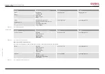
Parts list
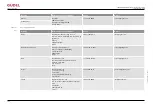
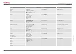
The parts list contains all parts of your product. The spare parts and wear
items are indicated as described in the explanation of symbols.
14.07.2008 / Page 1 of 1
VS0035
2-Amod ZP-4 M MO mec 3.10
10947-001A
E
t
i
n
U
y
t
i
t
n
a
u
Q
g
n
i
w
a
r
D
t
x
e
T
r
e
b
m
u
n
m
e
t
I
n
o
i
t
i
s
o
P
300
V000134
Y
k
t
S
1
2
3
0
-
3
2
5
8
0
0
2
9
=
L
V
5
2
-
0
2
2
/
0
2
2
P
L
s
i
x
A
-
E
k
t
S
7
7
0
.
0
0
2
.
7
1
.
0
9
3
S
U
G
I
0
.
0
0
2
.
7
1
.
0
9
3
n
i
a
h
c
y
g
r
e
n
E
4
0
0
1
4
1
0
2
0
3
400
0916667
Y
k
t
S
2
0
3
0
-
3
2
5
8
4
-
P
Z
e
g
a
i
r
r
a
C
-
900
406015-10.00
Worm gear unit AE060/L left
Ratio i=10.00
AE060
2
Stk
E
910
406089
Motor flange 060 18x116x116 ø130/110
8030-018a
2
Stk
E
1000
0910499
Mechanical multi limit switch accessories 750 Y
8523-024
2
Stk
1100
230803
Felt pinion for lubrication
ø40.6x20, Modul m=2.387 pitch P=7.5, Z=15
8102-039d
1
Stk
V
Güdel AG
Insustrie Nord
CH-4900 Langnethal
phone +41 62 916 91 91
fax +41 62 916 95 29
[email protected]
D000094
A
Fig. 12-1
Explanation of symbols
A
Spare part status
Spare part status (column E):
E
=
Spare part
V
=
Wear item
12.2.2
Position drawings
The positions of the spare parts can be seen on the drawings. These are stan-
dard drawings. Individual positions or images might differ from your product.
Spare parts supply
OPERATING MANUAL Automatic lubrication system
FlexxPump 402 / 402B
90071992656444683_v9.0_
EN-US
131

