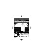
background image


iii

rev 12.14.15

Clevis

Pin

Hairpin Clip

Gate Bracket

Front Mount

Because automatic gate openers produce high levels of 

force, consumers need to know the potential hazards 

associated with improperly designed, installed, and 

maintained automated gate opener systems. 

Keep in 

mind that the gate opener is just one component of 

the total gate operating system.

 Each component must 

work in unison to provide the consumer with convenience, 

security, and safety.

This manual contains various safety precautions and 

warnings for the consumer. Because there are many 

possible applications of the gate opener, the safety 

precautions and warnings contained in this manual cannot 

Disconnecting the Opener


1. Turn control box power switch OFF.
2.  Remove hairpin clip, clevis pin, and bushing from both 

the front or rear mounting points.

3. Remove the opener from the mounts.

The gate can be opened and closed manually
when the opener is disconnected.

be completely exhaustive in nature. They do, however, 

provide an overview of the safe design, installation, 

and use of this product. 

CAREFULLY READ 

AND FOLLOW ALL SAFETY PRECAUTIONS, 

WARNINGS, AND INSTALLATION 

INSTRUCTIONS TO ENSURE THE SAFE 

SYSTEM DESIGN, INSTALLATION, AND USE 

OF THIS PRODUCT. 

Precautions and warnings in this manual are 

identified with this warning symbol. The symbol 

identifies conditions that can result in damage to the 

opener or its components, serious injury, or death.

Manually Opening and Closing Gate

Because GTO automatic gate openers are only part of the total gate operating system, it is the 

responsibility of the consumer to ensure that the total system is safe for its intended use.

CAUTION: The gate will move freely and uncontrolled when the gate opener is removed from 

the gate. ONLY disconnect the opener when the control box power switch is OFF and the gate is 

NOT moving.


NOTE:

 Substitute a

 Pin Lock (FM133)

 for the clevis pin on the front mount 

of the gate opener to prevent unauthorized removal of the opener from the gate 

(see accessory catalog)

.


IMPORTANT SAFETY INSTRUCTIONS

Summary of Contents for Mighty Mule FM200

Page 1: ...or more information on Mighty Mule s full line of Automatic Gate Openers and Access Controls visit www mightymule com 1 3 BU F N BZ N PWF BU BOZ U J N F P OPU BM M PX DIJ M ES FO U P PQFS BU F HBU F P...

Page 2: ...ener This gate opener produces a high level of force Stay clear of the unit while it is operating and exercise caution at all times All automatic gate openers are intended for use on vehicular gates o...

Page 3: ...Items Not Included xiv GATE OPERATOR INSTALLATION 1 CLOSED POSITION STOP PLATE INSTALLATION 3 CONTROL BOX AND BATTERY INSTALLATION 4 TRANSFORMER WIRING INSTALLATION 5 SOLAR PANEL INSTALLATION 6 SETTIN...

Page 4: ...Mule Gate Opener features adjustable obstruction sensing This safety feature makes the gate stop and reverse direction within 2 seconds when it comes in contact with an obstruction MIN is the factory...

Page 5: ...disconnected be completely exhaustive in nature They do however provide an overview of the safe design installation and use of this product CAREFULLY READ AND FOLLOW ALL SAFETY PRECAUTIONS WARNINGS AN...

Page 6: ...Make sure the gate has been properly installed and swings freely in both directions Repair or replace all worn or damaged gate hardware prior to installation A freely moving gate will require less fo...

Page 7: ...ere a user will be tempted to reach through the gate to activate the gate opener 5 Do not activate your gate opener unless you can see it and can determine that its area of travel is clear of people p...

Page 8: ...nges Apply silicone spray to a soft dry cloth and clean the push pull tube at least once a month 7 To operate this equipment safely YOU must know how to disconnect the operator for manual gate operati...

Page 9: ...te operator for entrapment protection functions shall be located where the transmission of the signals is not obstructed or impeded by building structures natural landscaping or similar obstruction A...

Page 10: ...te We recommend using a Pedestrian Gate Lock Call the GTO Sales Department at 800 543 4283 for controlled access Required Safety Precautions for Gates Install Warning Signs IMPORTANT SAFETY INFORMATIO...

Page 11: ...283 for free replacements Logo and warning labels 2 installed on each side of opener housing Control box label 1 installed on front of control box If any of these signs or warning decals become damage...

Page 12: ...point to mounting point Maximum stroke is 13 Adjustable auto close timer OFF 3 to 120 seconds and obstruction sensitivity Power terminal block accommodates a transformer or solar panels Accessory ter...

Page 13: ...charging power to charge the battery FM121 Refer to the Solar Panel and Gate Activity chart below All low voltage wire used with the GTO Gate Operator must be 16 gauge dual conductor stranded direct b...

Page 14: ...he operator is activated Make sure there is a stable area for mounting the gate bracket this may require the addition of a horizontal or vertical cross member We recommend you position the operator ne...

Page 15: ...Lock Nut 1 Hairpin Clip 2 2 Mounting Screw 3 1 K E E P C L E A R G a t e m a y m o v e a t a n y t i m e 2 D o n o t a l l o w c h i l d r e n t o o p e r a t e g a t e o r p l a y i n g a t e a r e a...

Page 16: ...uit If your gate is more than 1000 away from an ac power source you will need to use at least one Mighty Mule 5 watt solar panel to trickle charge the battery See the accessory catalog Do not use both...

Page 17: ...t any tim e 2 Do not allo w chil dre n to ope rate gat e or pla y in gat e are a 3 Thi s gat e is for veh icle s onl y Ped estr ian s mu st use a sep ara te ent ran ce Moving Gate Can Cause Injury Or...

Page 18: ...te cross support Attach post bracket assembly to fence post NOTE Must be through bolted GATE OPERATOR INSTALLATION 1 3 5 11 1 KEE P CLE AR Gat e ma y mo ve at any tim e 2 Do not allo w chil dre n to o...

Page 19: ...st use a sep ara te ent ran ce Moving Gate Can Cause Injury Or Death WARNIN G 15 4 J 1 2 1 1 2 Attach and secure opener assembly to brackets Attach gate bracket assembly to gate cross support Check fo...

Page 20: ...may move at any time 2 Do not allow child ren to opera te gate or play in gate area 3 This gate is for vehic les only Pede strian s must use a sepa rate entra nce Mo vin g Ga te Can Cause Injury Or De...

Page 21: ...S E TIM E MIN MA X STALL FO RC E 3 POWER OFF 120 AUTO CLOSE TIME MIN MAX STALL FORCE ON OFF SG1 ED1 K1 06 AVR ISP D1 C2 C7 C15 LED3 D15 R20 IC4 D16 D13 D14 K2 BATT BATT STATUS ANT SHLD S9 8874 EDGE CO...

Page 22: ...F1 VAR6 WHT GTO Inc Tallahassee FL CYCLE EXIT SAFETY COM CHGR CHGR Correct Wrong Wrong Wire Screwedinto wireinsulation Exposedstrands ofwire 5 POWER ON OFF SG1 ED1 K1 06 AVR ISP D1 C2 C7 C15 LED3 D15...

Page 23: ...transmitters are set to a standard code at the factory and are ready to operate your gate opener For your safety and security however we strongly recommend that you replace the factory setting with yo...

Page 24: ...need to increase the stall force See page 9 1 POWER ON OFF SG1 ED1 K1 06 AVR ISP D1 C2 C7 C15 LED3 D15 R20 IC4 D16 D13 D14 K2 BATT BATT STATUS ANT SHLD S9 8874 EDGE COM LOCK LOCK PGOK200 Rev XC M_BLK...

Page 25: ...K1 06 AVR ISP D1 C2 C7 C15 LED3 D15 R20 IC4 D16 D13 D14 K2 BATT BATT STATUS ANT SHLD S9 8874 EDGE COM LOCK LOCK PGOK200 Rev XC M_BLK M_RED VAR2 GRN VAR3 VAR3 VAR 1 VAR4 VAR5 PF1 VAR6 WH T GTO Inc Tal...

Page 26: ...compatible products for your specific application Make sure the power to the opener is turned off before connecting safety device wiring to the terminal blocks Unplugging the transformer does not turn...

Page 27: ...input while at open limit will restart the auto close time if enabled 6 CYCLE Typically for use with doorbell button or hardwired keypad Each activation at this input will cycle the operation as follo...

Page 28: ...efer to Vehicle Sensor manual for additional information if needed Edge Sensor GTO Lock NOTE Connections are for typical applications For additional connection options not illustrated here refer to th...

Page 29: ...Path of Gate Gate for Level and Plumb Stall Force Adjustment Disconnect Safety Devices 1 beep with 20 seconds off Low Battery Condition Transformer or Solar Panel Voltage Battery Harness Connections...

Page 30: ...Power Present Normal Operation Power green OFF No AC or Solar Power Transformer Breaker or GFI Power at AC outlet Output of Transformer Voltage on wire at 18 VAC Input Solar Solar Panel Wires Reversed...

Page 31: ...on the outside of the package in LARGE BOLD PRINT Ship the package s freight prepaid to GTO Access Systems LLC 3121 Hartsfield Road Tallahassee Florida USA 32303 If your Mighty Mule Gate Opener is no...

Page 32: ...Find Symbol centimeters 0 3937 inches in or meters 3 2808 feet ft or kilograms 2 2046 pounds lb or Converting English Units to Metric Equivalents When You Know Multiply By To Find Symbol inches 2 540...

Page 33: ...Mule entry transmitter with adjustable code settings is standard equipment with all Mighty Mule systems battery is included Digital Keypad FM137 Allow friends access to your property using an identif...

Page 34: ...9U NB The Garage Door Receiver allows you to use the same 2 button Mighty Mule entry transmitter to operate your gate operator and your garage door operator Compatible with most garage door operators...

Page 35: ...Notes NOTES...

Page 36: ...Hartsfield Road Tallahassee Florida USA 32303 Telephone GTO Sales 1 800 543 4283 Fax 850 575 8912 or GTO Technical Service 1 800 543 1236 Fax 850 575 8950 www mightymule com America s 1 D I Y Gate Op...

Reviews: