


GTI Grid Series
4
System Function
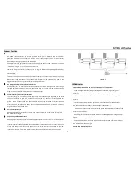
Connect to DC Power Resource directly and Direct-output Power Grid
DC power resource refers to devices included solar panels, batteries and wind power
generators with AC/DC controller, etc. All DC power supply output voltage fit with inverter
input voltage setting range which is 10.8-28VDC.
Power grid refers to single phase civil electricity utility grid. Such as 110V
(
90-140V
)
and 220V
(
190-260V
)
single phase civil electricity utility grid.
YSmartgrid tie microinverters can connect to power grid directly and uploading electric power
directly because of inverter output current wave form is pure sine wave which is same as civil
electricity grid.
There must be electricity on power grid and connectivity is first necessity of inverter operating.
When there is power outage or fault of power grid, inverters will be not operating. And it is the
biggest difference between grid tie inverter and off-grid inverter.
AC 0 Angle Phase High Precision Auto-detection
MCU process for high-precision detection and analysis after AC 0 angle phase pass through
isolation amplifier and input into MCU, phase shift rate is less than 1%, and finally achieving
high-precision of cophasal modulation AC combined Output.
Synchronous High-frequency Modulation
In process for grid connectivity, usually approach with cophasal angle for grid(ie, when total
current of inverter and grid is 0, combined current by switch). But our inverter approach for
grid with same frequency and same phase is DC to AC first, then rectified AC current into pulse
electric which is half-frequency 100Hz, finally combined pulse electric modulation with current
of grid and then fed into power grid.
Pure Sine Wave Output
Adopting Sinusoida PWM process for pure sine wave output which is same wave form of grid.
No interference for grid.
Superstrong Shadow Resistance
Adopting high frequency conversion operating, less transmission loss will be. In cloudy days or
inadequate sunshine days, if only there is 3W-5W output from power supply and input into
inverter, inverter can be operate AC conversion. But of cause, output is proportional input. The
more input power the more output power and vice versa. Inverter can operate in such low
input power supply, it’s indicate inverter power conversion operating times can be up more
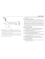
Figure 3
LED Indicator
1. Red LED indicator lights up under any conditions as listed below:
a. Low-voltage protection(DC input voltage lower than Min. input voltage of
inverters )
b. Over-voltage protection(DC input voltage higher than Max. input voltage of
inverters)
c. Over-temperature protection (inverters will be shut down for power output
when the temperature of body of inverters higher than 65-75
℃
.)
And inverter will be automatically restart up when the temperature of body of the
inverter down to 40-50
℃
.
d. Power grid fault protection (when 110VAC or 220VAC grid power outage and/or
tripped.
e. Islanding protection: inverter will be automatically shut down for power output
when disconnect with power grid.
2. Green LED Indicator Operation:


