


4. Electric Operated Gate Installation
34
PNEG-1993
CE Compliant E-Series Chain Conveyors - All Models
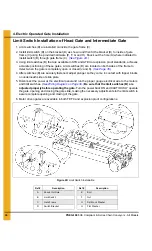
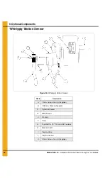
Limit Switch Installation of Head Gate and Intermediate Gate
1. Limit switches (B) are installed on inside the gate frame (C).
2. Install limit switch (B) on the bracket (D) as shown and then fit the bracket (D) to inside of gate
frame (C) using the provided hardware (E, F, G and H). Knock out the hole (A) where indicated to
install switch (B) through gate frame (C).
3. Using limit switches (B) that are available in STD and ATEX or explosion proof standards, achieves
accurate positioning of these gates. Limit switches (B) are located on both sides of the frame to
detect when the gate is completely open or closed (J and K).
4. After switches (B) are securely fastened, adjust plunger so they come in contact with tripper blocks
on underneath side of slide plate.
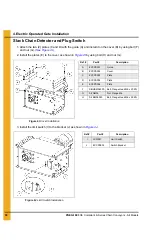
5. Disconnect the power at the electrical panel and run the proper gauge electrical wire to the motors
(See Wiring Diagram on Page 39.)
Be sure that the limit switches (B) are
adjusted properly before operating the gate.
Turn the power back ON and CAUTIOUSLY operate
the gate, opening and closing the gate slide, making the necessary adjustments to the limit switch to
assure complete opening and closing of the gate.
6. Motor driven gates are available in both TEFC and explosion proof configurations.
Figure 4D Limit Switch Installation
Ref #
Description
Ref #
Description
A
Knock Out Hole
E
Bolt
B
Limit Switch
F
Nut
C
Gate Frame
G
Split Lock Washer
D
Switch Bracket
H
Flat Washer


