GSI Group 1200 Bu/Hr Owner'S Manual Download Page 26

26

PNEG-1355 4" & 5" Air Systems

7. ASSEMBLY

7. Tripped Overload Indicator Light: This lamp will light up when any of the motor thermal 

overloads in the control box has tripped. The overloads for all three circuits (Aux, Airlock, 
and Blower) must have thermal overloads installed to operate the system. See Thermal 
Unit chart Drawing on 

page 27

8. 5 Amp Fuse: A five (5) Amp fuse protects the electrical components in the control box.

9. Control Switches: The operation of the blower, airlock and auxiliary equipment of the air 

system is controlled by placing these switches in the “Auto”, “Manual” or “Off” position.

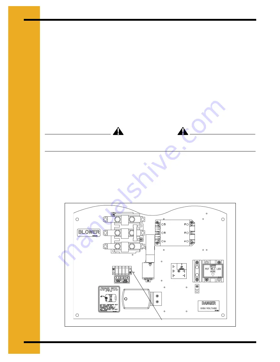
10. Automatic Control Terminals: When the air system is ready to run (i.e., the control ready 

light is on), the system can then be started and run by completing the circuit between 
terminals one (1) and two (2). The blower, airlock or auxiliary equipment will not run in the 
automatic mode unless terminals one (1) and two (2) are connected. For example, a 
closing set of contacts in a dryer control box would complete the circuit between terminals 
one (1) and two (2) and automatically start the air system. 

(See Figure 7M)

.

No voltage should be supplied to terminals one (1) and two (2). See the diagram 

on Page 28-33

 and drawing below.

11. Remote Shut-Down Control: A remote piece of equipment can be caused to shutdown with 

the air system by putting terminals three (3) and four (4) in series with the control circuit of 
the remote equipment. This circuit has a maximum current rating of 10 Amps. The circuit 
between terminals three (3) and four (4) is closed whenever the control circuit ready light 
is on, regardless of the position of the control switches. (“AUTO”, “OFF” or “ON”) See the 
Diagram on 

Page 28-33

 an

page 38

Figure 7M 

WARNING

Steps 10 & 11: Automatic Control and Remote Shut-Down Control

Summary of Contents for 1200 Bu/Hr

Page 1: ...PNEG 1355 Pneumatic Grain Conveying 4 700 Bu Hr 5 1200 Bu Hr 5 1700 Bu Hr Owner s Manual PNEG 1355 Date 03 29 07 ...

Page 2: ...2 PNEG 1355 4 5 Air Systems ...

Page 3: ...nts 18 Chapter 7 Assembly 19 Air System Set Up Procedures 19 Air System Control Box Definitions 25 Chapter 8 O L Thermals 27 Chapter 9 Wiring 28 Standard Schematic With Digital Amp Meter 28 Standard Schematic With Analog Amp Meter Using 2EL0273 Control Relay 29 Schematic With Analog Amp Meter Using HF 7203 Control Relay 30 Twin Schematic With Digital Amp Meter 31 Twin Schematic With Analog Amp Met...

Page 4: ... Switch Panel Assembly Twin 57 Standard Control Panel Assembly 230 V 10 30 HP 58 Standard Control Panel Assembly 230 V 10 30 HP Used In 8015071 Control Box CSA Listed 60 Standard Control Panel Assembly 230 V 40 HP 62 Twin Control Panel Assembly 230 V 7 15 HP 64 Twin Control Panel Assembly 230 V 7 15 HP Used in 8015114 Control Box CSA Listed 66 Standard Control Panel Assembly 460 V 10 40 HP 68 Cont...

Page 5: ... of the equipment and may lead to serious injury or death This is the safety alert symbol It is used to alert you to potential personal injury hazards Obey all safety messages that follow this symbol to avoid possible injury or death DANGER indicates an imminently hazardous situation which if not avoided will result in death or serious injury WARNING indicates a potentially hazardous situation whi...

Page 6: ...understand any part of this manual and need assistance contact your dealer Stay Clear of Moving Parts and Air valves Keep hands and feet away from moving parts Be sure all people are clear of the equipment before start up Wear close fitting clothing Keep all shields and covers in place at all times Stay clear of air blast for valve Always wear safety glasses to protect your eyes Install and Use eq...

Page 7: ...ng adjustments cleaning or maintaining equipment Keep all parts in good condition and properly installed Fix damage immediately Replace worn or broken parts Remove any build up of grease oil or debris Prepare for Emergencies Be prepared if fire starts Keep a first aid kit and fire extinguisher handy Keep emergency numbers for doctors ambulance service hospital and fire department near your telepho...

Page 8: ... to protect your hands from sharp edges on plastic or steel parts Wear steel toe boots to help protect your toes from falling debris A respirator may be needed if a hog house has poor ventilation Waste fumes can be toxic Remove all jewelry Tuck in any loose or dangling shoe strings Long hair should be tied up and back Wear hard hat to help protect your head Eye Protection Gloves Steel Toe Boots Re...

Page 9: ... easily readable and in good condition If a decal cannot be easily read for any reason or has been painted over replace it immediately Contact your dealer or the manufacturer to order a replacement decal free of charge For decal replacements contact GSI at 1004 E Illinois Street Assumption IL 62510 Ph 217 226 442 DC 1749 DC 994 N10080 DC 1382 N10090 ...

Page 10: ...10 PNEG 1355 4 5 Air Systems 2 DECALS DC 1386 DC 995 N10080 DC 994 DC 995 ...

Page 11: ...oots Blower Prior to 2004 2 Chain 3 Blowers Gearbox 1 Grease bearings until grease comes out of relief fitting Shell Darina NLGI Grade 2 2 Oil 3 Check oil levels 1500 Hours Synthetic Oil 500 Hours Standard Oil 1 Roots Flo and Duraflow 2 Roots Blower Prior to 2004 3 Roots Blower 2004 Later 1 Drain oil and replace with 1 5 Qts of DMC MS5389 synthetic oil Fill to middle of sight glass 2 Drain oil and...

Page 12: ...ty Chart 4 5 Systems Effective Length Feet 700 Bu Hr 4 System Roots 1200 Bu Hr 5 System Roots 1700 Bu Hr 5 System Roots Flo 10 HP Motor 15 HP Motor 20 HP Motor 20 HP Motor 30 HP Motor 20 HP Motor 30 HP Motor 40 HP Motor 50 525 800 850 1100 1300 1200 1600 1800 100 500 775 825 1075 1275 1175 1575 1775 150 475 750 800 1050 1250 1150 1550 1750 200 450 700 750 1000 1200 1100 1500 1700 250 400 650 700 9...

Page 13: ...ect the discharge chute Note A minimum of 10 feet is needed between the airlock discharge and the first elbow in the system 4 Determine the best routing of the galvanized steel pipe from the airlock to the storage areas Use galvanized elbows for changing the grain direction This will give better performance and longer life than flexhose 5 Bolt the tube mounting brackets to the desired location usi...

Page 14: ...ing can be attached to the deadhead down spout if needed If a cyclone is used an elbow and mounting brackets are needed 12 Select a location to mount the electrical control box that is accessible and easily reached should shut down of unit be necessary It should be close enough to the blower to run the 30 feet of rubber pressure hose between the blower and the control box Otherwise a longer length...

Page 15: ...PNEG 1355 4 5 Air Systems 15 NOTES ...

Page 16: ...16 PNEG 1355 4 5 Air Systems 5 INSTALLATION Air System Tubing Dimensions Figure 5B ...

Page 17: ... 29 29 46 3 1 2 7 1 8 9 10 5 12 1 13 9 15 5 17 1 20 5 35 27 19 45 2 1 2 8 6 10 2 11 10 13 6 15 2 16 10 18 6 21 10 5 25 32 1 2 22 1 2 50 4 1 2 7 8 9 10 6 12 3 14 15 9 17 6 21 30 30 1 2 30 1 2 49 3 1 4 6 10 8 7 10 4 12 1 13 10 15 7 17 4 20 10 35 28 1 2 18 1 2 48 2 1 4 8 6 10 3 12 13 9 15 6 17 3 19 22 6 6 25 32 1 4 22 1 4 51 4 1 2 7 3 9 1 10 11 12 9 14 7 16 5 18 3 21 11 30 30 1 4 30 50 3 7 1 8 11 10 ...

Page 18: ...18 PNEG 1355 4 5 Air Systems 6 DIMENSIONS Elbow Angle Measurements 801A025 8011235 8021120 802A015 804A014 8041124 L 10 8911 x Deg L 10 8813 x Deg L 10 873 x Deg ...

Page 19: ...ed 2 Place the air filter element with pre filter on the base and cover with the filter canister using the 3 8 wing nut and washer The wing nut does not need to be more than finger tight See Figure 7A Figure 7A 3 Check the motor name plate for the correct motor frame size Remove the hardware shipped in the Motor Mounting Plate Locate the motor on the mounting plate using the hole pattern which ali...

Page 20: ...motor and align it with the blower pulley See Figure 7C Figure 7C 5 See Figure 7D Place the matching set of V belts on the pulleys Tighten the belts by evenly turning the cap screws clockwise Belts should have 3 8 deflection at ten pounds pressure per belt See Figure 7E Figure 7D ...

Page 21: ...ake up bolt closest to the rear of the motor This nut is located behind the flange of the blower base Adjust if necessary Tighten the 4 flange head bolts that secure the motor mounting plate to the blower base Re Install Drive Shield See Figure 7F Figure 7F Rotate the motor by hand and listen for any rubbing or knocking by either the motor or the blower When the motor is wired it must be checked f...

Page 22: ...ate Blower Until Correct Oil Level is Indicated The 4 roots blower has sight glasses on both ends Be sure oil levels are indicated on both sight glasses See Figure 7G Figure 7G 8 Using four 4 5 16 x 3 4 flange head bolts mount the motor to the airlock deck Place the specified pulley on to the motor shaft and align to pulley on gearbox See Figure 7H Figure 7H ...

Page 23: ...sion of 3 8 deflection at ten pounds of pressure by pulling motor away from gearbox Tighten the four 5 16 flange bolts on the motor base Replace the belt shield Figure 7I 10 Check the oil level in the gearbox by removing the plug and noting if the oil is at this level Add SAE 80 90 gear lubricant if required See Figure 7J Figure 7J ...

Page 24: ...4 PNEG 1355 4 5 Air Systems 7 ASSEMBLY 11 Remove 1 4 pipe plug in gate valve pipe Install gauge assembly and attach air hose See Figure 7K Figure 7K THE SET UP OF THE PNEUMATIC AIR SYSTEM IS NOW COMPLETE ...

Page 25: ...eives a signal to start 4 Start Stop Switch The start button must be pushed before any part of the Air System can be run Pushing the stop button will immediately stop all functions 5 Air Pressure Limit Control Switch When in the On position this switch will allow the air pressure switch to immediately shut down the air system whenever the air pressure exceeds preset conditions 6 Amp Meter The Amp ...

Page 26: ...als one 1 and two 2 The blower airlock or auxiliary equipment will not run in the automatic mode unless terminals one 1 and two 2 are connected For example a closing set of contacts in a dryer control box would complete the circuit between terminals one 1 and two 2 and automatically start the air system See Figure 7M No voltage should be supplied to terminals one 1 and two 2 See the diagram on Pag...

Page 27: ...L UNIT 1EL0804 CC 74 6 THERMAL UNIT 1EL0791 CC 112 THERMAL UNIT 1EL0812 CC 156 THERMAL UNIT 4 700 10HP 230V 1PH 3 3 3 4 700 10HP 230V 3PH 3 3 3 4 700 10HP 440V 3PH 3 3 3 4 700 15HP 230V 1PH 3 3 3 4 700 15HP 230V 3PH 3 3 3 4 700 15HP 440V 3PH 3 3 3 4 700 20HP 230V 3PH 3 3 3 4 700 20HP 440V 3PH 3 3 3 5 1200 20HP 230V 3PH 3 3 3 5 1200 20HP 440V 3 PH 3 3 3 5 1200 30HP 230V 3PH 3 3 3 5 1200 30HP 440V 3...

Page 28: ...28 PNEG 1355 4 5 Air Systems 9 WIRING Standard Schematic With Digital Amp Meter ...

Page 29: ...PNEG 1355 4 5 Air Systems 29 9 WIRING Standard Schematic With Analog Amp Meter Using 2EL0273 Control Relay ...

Page 30: ...30 PNEG 1355 4 5 Air Systems 9 WIRING Schematic With Analog Amp Meter Using HF 7203 Control Relay ...

Page 31: ...PNEG 1355 4 5 Air Systems 31 9 WIRING Twin Schematic With Digital Amp Meter ...

Page 32: ...32 PNEG 1355 4 5 Air Systems 9 WIRING Twin Schematic With Analog Amp Meter Using 2EL0273 Control Relay ...

Page 33: ...PNEG 1355 4 5 Air Systems 33 9 WIRING Twin Schematic With Analog Amp Meter Using HF 7203 Control Relay ...

Page 34: ...e system 7 The airlock auxiliary equipment and blower will run when the control switches are placed in the manual mode The airlock auxiliary equipment and blower will stop immediately when switched off 8 Pushing the Stop button will immediately stop all air system functions as well as any equipment tied to terminals three 3 and four 4 Operation of the air system WITHOUT an Automatic Controller tie...

Page 35: ...irlock and auxiliary equipment to Off and the blower to Manual Note the opening of the outlet gate valve then open it completely so all the air is exhausted when the blower is started Push the start button and the blower will start Slowly close the outlet gate valve until the grain starts moving and clears the tube Adjust the valve as explained in Step 1 It should be the same as noted before adjus...

Page 36: ...5 system running full with 30 HP will have a system pressure of 5 6 psi A 5 system running full with 40 HP will have a system pressure of 6 7 psi 7 OPERATION OF TWIN MOTOR TRANSFER OPTION The Twin Motor Option allows an air system to use two single phase motors to provide extra power when 3 phase electricity is not available The Twin Motor Control box is different from the standard control box bec...

Page 37: ...hould be coated with motor oil after each drying season Spray lubricants such as WD 40 do not usually provide adequate protection Both the airlock and blower assemblies should be carefully protected from the weather and the piping system disconnected from the blower and airlock Remove the transition connection to the airlock inlet and re install the weather cover shipped with the airlock This is i...

Page 38: ...O REMOTE EQUIPMENT Any contact that closes upon start and opens on stop Note This contact must not have any external AC Power Remote Equipment Control Circuit With the above hook up the Air System must be started before the remote equipment If the Air System is manually turned off or turned off from high pressure or an overload the remote equipment will also turn off TB3 and TB4 will have a closed...

Page 39: ...alog 10 Switch Panel Assembly Standard 11 Switch Panel Assembly Twin 12 Standard Control Panel Assembly 230 V 10 30 HP 13 Standard Control Panel Assembly 230 V 10 30 HP Used In 8015071 Control Box CSA Listed 14 Standard Control Panel Assembly 230 V 40 HP 15 Twin Control Panel Assembly 230 V 7 15 HP 16 Twin Control Panel Assembly 230 V 7 15 HP Used in 8015114 Control Box CSA Listed 17 Standard Cont...

Page 40: ...40 PNEG 1355 4 5 Air Systems 12 PARTS LIST 4 700 5 1200 Standard Blower Parts ...

Page 41: ...1 Zn GR5 12 AS 0025 2 2 Motor Adjust Rail Asy 13 AS 0042 1 1 Blower Suppt shim Asy 4 5 14 PT0664 1 Pulley Qd 7 75OD x Sk Bush 3AB PT0602 1 Pulley Solid 5 50 Od x SD 3AB 15 PT0772 1 Bushing QD Style Sk 1 1 8 Bore PT0794 1 Bushing SD X 1 1 8 Bore 16 MHC00028 3 Belt V B x 60 PT1179 3 Belt V B x 58 17 801L001 1 Logo Decal Transfer 700 8027012 1 Logo Decal Transfer 1200 420 1443 1 1 1 Logo Decal FFI 18...

Page 42: ...42 PNEG 1355 4 5 Air Systems 12 PARTS LIST 4 5 Twin Blower Parts ...

Page 43: ...r 5 STD Twin DMC AS 0054 F 1 Elbow Asy blower 5 STD Twin FFI 14 PT0742 1 Pulley QD 7 75OD x Sk Bush 4AB PT0741 1 Pulley 5 50OD x SD BSH 4AB 15 PT0772 1 Bushing qd Style Sk 1 1 8 Bore PT0794 1 Bushing Sd X 1 1 8 Bore 16 MHC00028 2 Belt V B x 60 MHC00743 2 Belt V B x 65 17 MHC00020 2 Belt V B x 68 MHC00743 2 Belt V B x 65 18 AS 0085 1 1 Support Angle blower Outlet TW 19 S 6606 1 1 Bolt Flngs 5 16 18...

Page 44: ...44 PNEG 1355 4 5 Air Systems 12 PARTS LIST 5 1700 Hi Capacity Blower Parts ...

Page 45: ...S 858 2 Washer Flat 5 8 Uss Zn 11 2FH1043 2 Bolt 5 8 11 x 3 1 2 HHTB GR2 PLT 12 AS 0025 2 Motor Adjust Rail Asy 13 PT0736 1 Pulley 4 95 OD x SD BSH 4AB 14 GC06682 1 Bushing SD X 1 7 16 Bore 15 MHC00028 4 Belt V B x 60 16 8021130 RD 1 Blower Inlet 5 HI RED 8021130 OR 1 Blower Inlet 5 HI ORANGE 17 S 9259 1 Nut Flangwz 5 8 11 Zn 18 DC 1330 1 Logo Decal DMC 2 7 8 X 9 19 420 1443 1 1 Logo Decal FFI 802...

Page 46: ...46 PNEG 1355 4 5 Air Systems 12 PARTS LIST 5 1700 Twin Hi Capacity Blower Parts ...

Page 47: ...sy blower Out 5 HI Twin DMC AS 0051 F 1 Elbow Asy blower Out 5 HI Twin FFI 13 8021130 RD 1 Blower Inlet 5 HI RED 8021130 OR 1 Blower Inlet 5 HI ORANGE 14 PT0736 1 Pulley 4 95 OD x SD BSH 4AB 15 MHC00028 2 Belt V B x 60 16 MHC00743 2 Belt V B x 65 17 GC06682 1 Bushing SD x 1 7 16 Bore 18 S 9259 2 Nut Flangwz 5 8 11 Zn 19 AS 0085 1 Support Angle blower Outlet Twin 20 S 6606 1 Bolt Flngs 5 16 18 x 3 ...

Page 48: ...48 PNEG 1355 4 5 Air Systems 12 PARTS LIST 4 5 Blower Filters ...

Page 49: ...Filter Base 5 Assembly DMC 802A072 F 1 Filter Base 5 Assembly FFI 4 8021219 D 1 Filter Canister w Inlet Assembly Precleaner DMC 8021219 F 1 Filter Canister w Inlet Assembly Precleaner FFI 5 801A154 1 Filter Inner 10 Micron Part of 801A152 6 801A156 1 Filter Outer Pre Foam Part of 801A152 7 S 1451 1 Nut Wing 3 8 16 UNC Plated 8 8021228 1 Plate Filter Top Precleaner 4 5 Air Systems 9 MS5466 1 Precle...

Page 50: ...50 PNEG 1355 4 5 Air Systems 12 PARTS LIST 4 5 Airlock Parts ...

Page 51: ...0622 1 1 Pulley Flat 3 x 1 ID 1A 11 AS 0109 1 1 Airlock Belt Guard Asy Prior 8 05 AS 0124 1 1 Airlock Belt Guard Asy 8 05 12 AS 0070 1 Inlet Asy 4 Airlock AS 0072 1 Inlet Asy 5 Airlock 13 801A205 1 Chain roller 4 Airlock 801A148 1 Chain roller 5 Airlock 14 KD PRC6001 1 1 Link Connecting 60 3 4 Pitch 15 PT1054 1 1 Link Offset 60 3 4 Pitch 16 PT1083 1 Sprocket Hub 15t 1 5 ID 60 PT1107 1 Sprocket Hub...

Page 52: ...52 PNEG 1355 4 5 Air Systems 12 PARTS LIST Airlock Inlet Transition Assembly ...

Page 53: ...mine what direction the airlock grain line is to run orient the transition assembly to correspond with the line direction attach the transition assembly to the airlock inlet using S 8857 Item 4 and S 7215 Item 5 4 Trim the top of the transition assembly to match the height of the dryer discharge Ref Part Qty Description 1 AS 0077 2 Airlock Inlet Trans RH LH 2 AS 0078 2 Airlock Trans Front Back 3 S...

Page 54: ...kscreen Digi amp DMC 1 8015121D 1AR Panel W Silkscreen Digi amp FFI 2 PT1125 1 Gauge Pressure 2 1 2 15 PSI 3 4FH0452 1 Fit elbow street 90 1 4 NPT 4 4FH1122 1 Fit hose Barb 1 4 x 1 4 Brass 5 AS 0211A 1 Digital Amp Meter Asy W Jumper 6 TFH 2021 3 Light Red Neon No Leads 125 VAC 7 1EL0826 1 Fuseholder Panmnt CSA 30A 250 V 8 1EL0754 1 Fuse AGC5 250 V 5 Amp ...

Page 55: ...el Deadfront DMC 1 8015121 1 Single Main Panel Deadfront FFI 2 PT1125 1 Gauge Pressure 2 1 2 15 PSI 3 2EL0290 1 Amp Meter Panel 0 150 Amp 4 TFH 2021 3 Light Red Neon Spade Term 125 VAC 5 1EL0826 1 Fuseholder Panel Mount 30a 250 V 6 1EL0719 1 Fuse AGC 2 250 V 2 Amp 7 4FH0452 1 Fitting elbow street 90 1 4 NPT 8 4FH1122 1 Fitting hose Barb 1 4 x 1 4 Brass ...

Page 56: ...ly Standard Switch Panel Assembly Standard Ref Part Qty Description 1 8015078 1 Switch Panel Standard 2 2EL0668 3 Lever Switch SPDT ON OFF ON 3 2EL0659 1 Lever Switch SPDT ON NONE ON 4 2EL0618 1 Pushbutton Switch SPST START 5 2EL0619 1 Pushbutton Switch SPST STOP ...

Page 57: ...Assembly Twin Switch Panel Assembly Twin Ref Part Qty Description 1 8015110 1 Switch Panel Twin 2 2EL0659 2 Lever Switch Spdt ON NONE ON 3 2EL0618 1 Pushbutton Switch SPST START 4 2EL0619 1 Pushbutton Switch SPST STOP 5 2EL0668 4 Lever Switch SPDT ON OFF ON ...

Page 58: ...58 PNEG 1355 4 5 Air Systems 12 PARTS LIST Standard Control Panel Assembly 230 V 10 30 HP ...

Page 59: ...PHP Zn 10 2EL0307 1 Transformer current 150 5 Ratio 2EL0368 1 Transformer current 200 5 Ratio 11 2EL0273 1 1 Relay 3 PDT 5A 120 V Deltro 12 801E047 1 1 Timer Off Delay 15 Sec Asy 13 S 7124 1 1 Screw Tcsf 8 32 x 1 PHP Zn 14 1EL0909 1 1 Pwr Dist Blk 175A 600 V 1P 15 C 8018 1 1 Terminal Block 185A 3 Pole 1 4 16 E160 1137 1 1 Lug Ground TA 2 CSA 17 801E018 1 1 High Pressure Switch Asy 18 602L013 1 1 D...

Page 60: ...60 PNEG 1355 4 5 Air Systems 12 PARTS LIST Standard Control Panel Assembly 230 V 10 30 HP Used In 8015071 Control Box CSA Listed ...

Page 61: ...SA 90 Amp 9 S 6557 6 Screw TCSF 8 32 x 3 4 PHP Zn 10 2EL0307 1 Transformer Current 150 5 Ratio 11 801E047 1 Timer off Delay 15 Sec Asy 12 S 7124 3 Screw Tcsf 8 32 x 1 PHP Zn 13 7097555 1 Relay Base 3 PDT Small Square 14 HF 7203 1 Relay 3 PDT 120 V RH3B U IDEC 15 1EL0909 1 Pwr Dist Blk 175A 600 V 1P 16 C 8018 1 Terminal Block 185A 3 Pole 1 4 17 E160 1137 1 Lug Ground TA 2 CSA 18 801E018 1 High Pres...

Page 62: ...62 PNEG 1355 4 5 Air Systems 12 PARTS LIST Standard Control Panel Assembly 230 V 40 HP ...

Page 63: ...ff Delay 15 SEC Asy 11 S 7124 1 1 Screw TCSF 8 32 x 1 PHP Zn 12 1EL0909 1 1 Pwr Dist Blk 175A 600 V 1P 13 C 8018 1 1 Terminal Block 185A 3 Pole 1 4 14 E160 1137 1 1 Lug Ground TA 2 CSA 15 801E018 1 1 High Pressure Switch Asy 16 801L003 1 1 Decal Pressure Switch 17 602L013 1 1 Decal Wild Leg 18 802L006 1 1 Decal Auxiliary 19 802L005 1 1 Decal Airlock 20 802L004 1 1 Decal Blower 21 2EL0249 1 1 Conta...

Page 64: ...64 PNEG 1355 4 5 Air Systems 12 PARTS LIST Twin Control Panel Assembly 230 V 7 15 HP ...

Page 65: ...07 2 Transformer Current 150 5 Ratio 11 2EL0368 2 Transformer Current 200 5 Ratio 12 S 3674 4 4 Washer Flat 10 Sae Zn 13 8017033 1 1 Decal Blower 1 14 8017034 1 1 Decal Blower 2 15 1773 1 1 Terminal Block 4 Pole 2 Row 16 801L006 1 1 Decal Terminal Strip 17 801E018 1 1 High Pressure Switch Asy 18 801L003 1 1 Decal Pressure Switch 19 801E047 1 1 Timer Off Delay 15 Sec Asy 20 S 7124 2 2 Screw Tcsf 8 ...

Page 66: ...66 PNEG 1355 4 5 Air Systems 12 PARTS LIST Twin Control Panel Assembly 230 V 7 15 HP Used in 8015114 Control Box CSA Listed ...

Page 67: ...L0282 2 Relay THRML Overload CSA 86 Amp 11 2EL0307 2 Transformer Current 150 5 Ratio 12 S 3674 4 Washer Flat 10 SAE Zn 13 8017033 1 Decal Blower 1 14 8017034 1 Decal Blower 2 15 1773 1 Terminal Block 4 Pole 2 Row 16 801L006 1 Decal Terminal Strip 17 801E018 1 High Pressure Switch Asy 18 801L003 1 Decal Pressure Switch 19 801E047 1 Timer Off Delay 15 Sec Asy 20 S 7124 4 Screw TCSF 8 32 x 1 PHP Zn 2...

Page 68: ...68 PNEG 1355 4 5 Air Systems 12 PARTS LIST Standard Control Panel Assembly 460 V 10 40 HP ...

Page 69: ...0 2EL0307 1 Transformer Current 150 5 Ratio 2EL0307 1 Transformer Current 200 5 Ratio 11 2EL0273 1 1 Relay 3 PDT 5A 120 V Deltro 12 801E047 1 1 Timer Off Delay 15 Sec Asy 13 S 7124 1 1 Screw TCSF 8 32 x 1 PHP Zn 14 1EL0909 1 1 Pwr Dist Blk 175A 600 V 1P 15 C 8018 1 1 Terminal Block 185A 3 Pole 1 4 16 E160 1137 1 1 Lug Ground TA 2 CSA 17 801E018 1 1 High Pressure Switch Asy 18 1773 1 1 Terminal Blo...

Page 70: ...70 PNEG 1355 4 5 Air Systems 12 PARTS LIST Control Panel Assembly 460 V 10 40 HP Used In 8015072 Control Box CSA Listed ...

Page 71: ... 9 S 6557 6 Screw TCSF 8 32 x 3 4 PHP Zn 10 2EL0307 1 Transformer Current 150 5ratio 11 801E047 1 Timer Off Delay 15 Sec Asy 12 S 7124 3 Screw TCSF 8 32 x 1 PHP Zn 13 7097555 1 Relay Base 3 PDT Small Square 14 HF 7203 1 Relay 3 PDT 120 V RH3B U IDEC 15 1EL0909 1 PWR Dist Blk 175A 600v 1p 16 C 8018 1 Terminal Block 185A 3 Pole 1 4 17 E160 1137 1 Lug Ground Ta 2 CSA 18 801E018 1 High Pressure Switch...

Page 72: ...er hose used to change grain direction or used for extended lengths 5 Airlock shear protector installed wrong 3 Airlock Stops or is Noisy 1 A foreign object may have become lodged in the airlock vanes 2 Check belt tension 3 Check gearbox drive 4 The rotor vanes may be rubbing on the ends of the airlock Check clearance at both ends of rotor and center in housing by loosening the set screws in the b...

Page 73: ...ry switches must be in either Auto or Manual to operate 2 The automatic control not wired correctly or not working Requires a closed contact across TB1 and TB2 to auto start 6 Blower Motor Trips Thermal Overload 1 Check current draw using Amp meter The motor should not be pulling more current than the name plate specifies Reduce feed rate if excessive 2 Check heater sizes 3 Check for loose connect...

Page 74: ...lide coupling over one pipe past end then butt pipe ends a small gap 1 16 maximum at butt joint will not reduce coupling performance Slide coupling back until coupling and gasket protector are centered over joint Use care when sliding coupling into place avoid wrinkling of gasket or gasket protector 5 The gasket protector provides a bleed path for static electricity 6 Partially tighten bolts evenl...

Page 75: ...SHALL NOT BE LIABLE FOR ANY DIRECT INDIRECT INCIDENTAL OR CONSEQUENTIAL DAMAGES INCLUDING WITHOUT LIMITATION LOSS OF ANTICIPATED PROFITS OR BENEFITS PURCHASER S SOLE AND EXCLUSIVE REMEDY IS AS SET FORTH IN THE LIMITED WARRANTY EXPRESSED ABOVE WHICH SHALL NOT EXCEED THE AMOUNT PAID FOR THE PRODUCT PURCHASED THIS WARRANTY IS NOT TRANSFERABLE AND APPLIES ONLY TO THE ORIGINAL PURCHASER GSI SHALL HAVE ...

Page 76: ...which should be carefully followed in all cases Authorities having jurisdiction should be consulted before installations are made GSI Group Inc 1004 E Illinois St Assumption IL 62510 0020 Phone 1 217 226 4421 Fax 1 217 226 4420 Internet http www grainsystems com Copyright 2007 by the GSI Group Printed in the USA ...

Reviews: