


Allgemeiner T
eil / General Section
M 100-ADPL
1 - 10
GRUNDIG
Service
Adapting the Surround mode values
The surround mode has programmed values for
centre-mode, centre and rear levels and for rear
channel time delay which are suitable for most
common applications.
You can , however, change these settings to your
particular taste or speaker installation.
To install your Surround system proceed as
follows:
• Press the
SURROUND INSTALL
key longer than
1,5 seconds.
– The display shows first ‘
INSTALL
’ and
changes then to e.g.‘
NORMAL
’.
• Use the
and
– REAR
buttons to
select the centre channel mode:
NORMAL
,
WIDE
or
PHANTOM
.
– Select
NORMAL
if you are using a normal
centre speaker.
– Select
WIDE
if you have connected a HiFi
centre speaker
– Select
PHANTOM
if you have not connected a
centre speaker, but still wish to simulate the
sound coming from the centre.
• Press the
SURROUND INSTALL
button again.
– The display shows e.g.
DELAY 20
.
• Use the
and
– REAR
buttons to
adjust the delay time of the rear channel
(between 15 and 30 ms). Increasing the rear
delay time expands the perceived listening
area, and vice versa.
ADAPTING THE SURROUND MODE VALUES
• Press the
SURROUND INSTALL
button again.
– You will now hear a test tone from the left,
centre, right and rear speakers in turn, in a
repeating cycle.
– The display shows e.g.
TEST FL
➡
TEST_C 0
➡
TEST FR
➡
TEST_R 0
➡
TEST FL
• The values of the centre and rear level can be
adjusted if you press
or
– REAR
during the 2 seconds that you hear the test
tone of the centre
TEST_C 0
and the rear
speaker
TEST_R 0
.
• When you are satisfied with the levels, press
the
SURROUND INSTALL
button again to turn
off the test tone and leave the installation mode.
Note:
When you have selected
PHANTOM
for the
centre channel mode, the test tone sequence will be
as follows:
TEST FL
➡
TEST FR
➡
TEST_R 0
➡
TEST FL
Direct adjustment of rear and centre level
During e.g. a film, it is possible that the special
effects on the rear speakers become too loud or
too quiet compared to the level of the dialogue,
making it necessary to perform small adjustments.
Your unit is, for this purpose, provided with two
keys for direct adjustment:
Adjusting the rear level
• Press the
– REAR
button.
The display shows e.g.
REAR 0
.
• If you press within 2 seconds the
or
– REAR
buttons you can adjust the rear level
(related to the front level).
Adjusting the centre level
• Press the
button.
The display shows e.g.
CENTRE 0
.
• If you press within 2 seconds the
or
– REAR
buttons you can adjust the centre level
(related to the front level).
SURROUND
INSTALL
> 1.5 SEC
– REAR
PRO-LOGIC
➥
➥
➥
➥
➡
➡
INSTALL
PRO-LOGIC
NORMAL
PRO-LOGIC
DELAY 20
PRO-LOGIC
TEST
PRO-LOGIC
TEST FL
PRO-LOGIC
TEST_C 0
PRO-LOGIC
TEST FR
PRO-LOGIC
TEST_R 0
SURROUND
INSTALL
➡
➡
SURROUND
INSTALL
➡
➥
➥
➥
➥
➥
– REAR
– REAR
– REAR
➥
➥
PRO-LOGIC
➡
REAR 0
➥
➥
– REAR
– REAR
PRO-LOGIC
➡
CENTRE 0
➥
➥
– REAR
Changing the batteries
If the range of your infrared remote control seems to
decrease, or if certain individual functions can no
longer be carried out, you should replace the
batteries.
Two micro 1.5 Volt LR03 size AAA are required. To
change the batteries, open the compartment on the
back of the remote control. Ensure that the batteries
are inserted properly (note the markings in the
compartment).
In the interest of the environment:
Remember that
batteries must always be disposed of properly.
General controls
y
HIFI
– To switch the HIFI system to STAND BY.
/–
– Controlling the volume of the
amplifier (provided the HIFI - TV/VCR switch is in
position HIFI).
a
– For muting the speakers (provided the HIFI -
TV/VCR switch is in position HIFI).
SURROUND INSTALL
This button is used to switch
between SURROUND (DOLBY PRO LOGIC) and
STEREO mode and to enter the installation mode for
surround settings.
REAR –
to call up rear level adjustment mode or to
manipulate the different surround settings
to call up centre level adjustment mode
or to manipulate the different surround settings
SYSTEM REMOTE CONTROL
To control the functions of the sources TUNER, CD
or TAPE, make sure that the HIFI - TV/VCR switch
is in the position HIFI
TUNER
TUNER/pty
– For selecting the radio and for
selecting the programme type (PTY) mode.
10-button keypad
for directly selecting stations
$ #
STATION
– For selecting stations, to select
programme types in the PTY mode or to select
characters in the station name input mode.
S T
– To start tuning up/down or to move
the cursor in the station name input mode.
TXT/
6
– To change the information shown in the
display or to enter the station name input mode.
CD
CD/disc
– For selecting the CD player and to enter
the disc selection mode when using a CD-changer.
10-button keypad
for directly selecting tracks
;
– To switch the CD player to PAUSE.
9
– To switch the CD player to STOP.
B
– To start and restart playback of the CD player.
S T
– To select next or previous tracks on a
CD, to search forward and backward or to select a
disc when using a CD-changer.
TXT/
6
– To change the information shown in the
display.
TAPE
TAPE
A B
– For selecting the cassette deck and for
selecting the tape travel direction.
B
– To start playback.
9
– To switch the cassette deck to STOP.
;
– To switch the cassette deck to PAUSE.
S T
– For fast winding of the tape in forward
or reverse direction or to search for next or previous
tracks during playback.
RECORD
0
– To start recording
1
2
3
4
5
6
7
8
9
0
STATION
VOLUME
SA
T
TV
TAPE
1
2
CD/disc
TUNER/pty
VCR
SA
T
TV
8
3
Z
T
1
A/V REMOTE CONTROL-URC1
E
a
P
P
P
HIFI
TV/VCR
HIFI
88
TXT/
6
P
P
P
AV
Install
–
+
CENTRE
SURROUND
REAR
$
#
2
RECORD
w
TV
TV
– For selecting the TV set (when connected to the
TV input).
y
TV
– To switch the TV to STAND BY.
– For selecting next or previous TV stations.
To control the following functions of the TV, make
sure that the HIFI - TV/VCR switch is in the
position TV/VCR
10-button keypad
for directly selecting stations .
TXT/
6
– For selecting teletext.
a
– For muting the speakers.
/–
– For controlling the volume of the
TV.
SAT
SAT
– For selecting the satellite receiver (when
connected to the TV input).
y
SAT
– To switch the satelite receiver to STAND
BY.
– For selecting next or previous satellite
programmes.
VCR
VCR
– For selecting the video recorder (when
connected to the VCR input).
– For selecting next or previous VCR stations.
To control the following functions of the video
recorder, make sure that the HIFI - TV/VCR switch
is in the position TV/VCR
B
– To start playback of the video recorder.
RECORD
0
– To start recording.
9
– To switch the video recorder to STOP.
;
– To switch the video recorder to PAUSE.
Q R
– Fast winding of the tape in forward or
reverse direction.
?
@@@@@@@@e@@@?f?
3@@@@@@5?J@@@Lf?
N@@@@@@H?7@@@1f?
?3@@@@5?J@@@@@L?e?
?N@@@(Y?7@@@@@1?e?
3@@H?J@@@@@@@Le?
V4@??@@@@@@@@@e?
?
?
@@@@@@@@e@@@?f?
3@@@@@@5?J@@@Lf?
N@@@@@@H?7@@@1f?
?3@@@@5?J@@@@@L?e?
?N@@@(Y?7@@@@@1?e?
3@@H?J@@@@@@@Le?
V4@??@@@@@@@@@e?
?
?
@@@@@@@@e@@@?f?
3@@@@@@5?J@@@Lf?
N@@@@@@H?7@@@1f?
?3@@@@5?J@@@@@L?e?
?N@@@(Y?7@@@@@1?e?
3@@H?J@@@@@@@Le?
V4@??@@@@@@@@@e?
?
SYSTEM REMOTE CONTROL
Operation of other brands
This remote control can be used to operate also
other brands of TV’s, Satellite receivers and Video
recorders. The codes for these other brands have
already been put in the memory.
For TV sets you can select 5 different presets, for
Satellite receivers 3 and for Video recorders 10
different presets.
How to select the right presets?
for TV sets
• Keep the TV button pressed and press one of the
number 1...5 of the numeric keys for approx. 6
seconds.
– On the display of your amplifier appears e.g.
TV 1
.
• To control if you have selected the right code,
press e.g. one of the
buttons.
– If your TV reacts to this command you have
selected the right preset.
– If your TV does not react, try to select another preset.
for Satellite receivers
• Keep the SAT button pressed and press number
1, 2 or 3 of the numeric keys for approx. 6
seconds.
– On the display of your amplifier appears e.g.
SAT 1
.
• To control if you have selected the right code,
press e.g. one of the
buttons.
– If your Satellite receiver reacts to this command
you have selected the right preset.
– If your Satellite receiver does not react, try to
select another preset.
for Video recorders
• Keep the VCR button pressed and press one of
the numeric keys (1...0) for approx. 6 seconds.
– On the display of your amplifier appears e.g.
VCR 1
.
• To control if you have selected the right code,
press e.g. one of the
buttons.
– If your VCR reacts to this command you have
selected the right preset.
– If your VCR does not react, try to select another preset.
?
@@@@@@@@e@@@?f?
3@@@@@@5?J@@@Lf?
N@@@@@@H?7@@@1f?
?3@@@@5?J@@@@@L?e?
?N@@@(Y?7@@@@@1?e?
3@@H?J@@@@@@@Le?
V4@??@@@@@@@@@e?
?
?
@@@@@@@@e@@@?f?
3@@@@@@5?J@@@Lf?
N@@@@@@H?7@@@1f?
?3@@@@5?J@@@@@L?e?
?N@@@(Y?7@@@@@1?e?
3@@H?J@@@@@@@Le?
V4@??@@@@@@@@@e?
?
?
@@@@@@@@e@@@?f?
3@@@@@@5?J@@@Lf?
N@@@@@@H?7@@@1f?
?3@@@@5?J@@@@@L?e?
?N@@@(Y?7@@@@@1?e?
3@@H?J@@@@@@@Le?
V4@??@@@@@@@@@e?
?
1
2
3
4
5
6
7
8
9
0
STATION
VOLUME
SA
T
TV
TAPE
1
2
CD/disc
TUNER/pty
VCR
SA
T
TV
8
3
Z
T
1
A/V REMOTE CONTROL-URC1
E
a
P
P
P
HIFI
TV/VCR
HIFI
88
TXT/
6
P
P
P
AV
Install
–
+
CENTRE
SURROUND
REAR
$
#
2
RECORD
w
Dolby Pro Logic
Dolby Pro Logic is a coding system that enables a
set to decode 4 sound channels out of a normal
stereo signal: the centre channel for picture related
sounds, both front left and right channels for stereo
sounds and one surround channel to bring room
and depth to the scene.
Dolby Pro Logic manufactured under license from
Dolby Laboratories Licensing Corporation.
DOLBY, the double-D symbol
and ‘PRO
LOGIC’ are trademarks of Dolby Laboratories
Licensing Corporation.
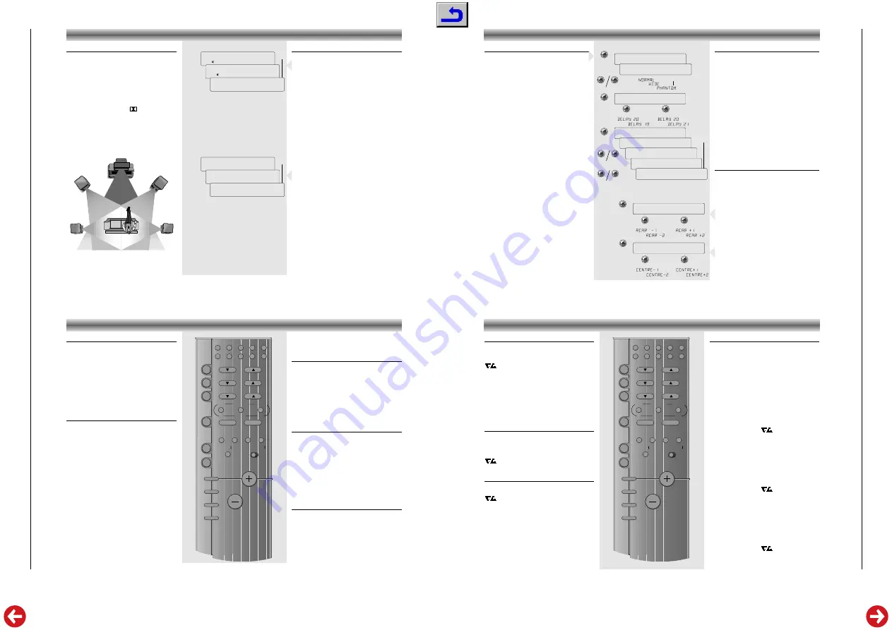
A full Pro Logic system needs 5 speakers that should
be connected and positioned as shown below.
LEFT
RIGHT
TV
CENTER
SURROUND
LEFT
SURROUND
RIGHT
SURROUND SOUND
PRO-LOGIC
VCR
➥
➥
➥
STEREO
VCR
➥
➥
➥
A
VCR
PRO-LOGIC
A
PROLOGIC
PRO-LOGIC
VCR
Selecting the surround mode
• Press briefly the
SURROUND INSTALL
button to
switch the surround mode on.
The display shows briefly
PROLOGIC
and then
the selected source again.
– The indication
PRO
-
LOGIC
remains on the display.
PRO LOGIC
Choose this setting for playback of music and
movies (especially Laser Discs, videocassettes and
TV broadcasts with DOLBY SURROUND sound).
Not only does Dolby Pro Logic surround you with
sound, it also gives you a clear perception of the
position and direction of the sound.
In this mode you use 5 speakers: front left and right,
a centre speaker and two rear speakers. .
• Press again briefly the
SURROUND INSTALL
button to switch the surround mode off.
The display shows briefly
STEREO
and then the
selected source again.
PRO
-
LOGIC
does not light
up anymore.
STEREO
In this case the centre and rear speakers are
switched off for normal stereo operation.
Note:
the surround mode Dolby Pro Logic will not
work properly if the signal passes through a graphic
equalizer. Please refer to your equalizer user
manual for guidance on switching off (or defeating)
the equalizer.


