


V 14 DPL-RF
Allgemeiner T
eil / Gener
al Section
GR
UNDIG
Ser
vice
1 - 9
Source selection
• To select a listening source, press either the
corresponding button on the unit or on the remote
control. The yellow LED next to the respective
button on the unit comes on and the display
indicates the selected source e.g.
TAPE
.
D.O.T. (Direct Operation Technique)
An "intelligent" data bus connection in your unit
makes it possible for individual components of this
series to "communicate" with each other.
The D.O.T. function allows automatic input selection
by the unit.
• E.g.: as soon as you press the CD player
PLAY
B
button, the tuner
STATION
1 2
buttons or the
cassette deck
PLAY
B
button, the unit
automatically switches to the corresponding input.
• To take advantage of this capability, all auxiliary
units must be connected via the bus lines (orange
connectors), and the D.O.T. function must be
active (D.O.T. switch on).
If D.O.T. is not active, the unit functions as a normal
unit. This may be desirable, for example, if you
want to listen to a CD over headphones and would
like to simultaneously make a tape recording from
another programme source, for instance, from the
tuner.
Switching off the display
Your unit is capable of controlling the displays of all
the units connected via the bus system.
• Use the
DISPLAYS ON/OFF
button if you want to
switch off the displays. Pressing this button again
switches all displays on once more.
SOURCE SELECTION
SELECTING SPEAKERS
LEFT
RIGHT
TV
CENTRE
RBX1-RF
RBX1-RF
ROOM B
ROOM A
HOME CINEMA
STEREO
TAPE
Switching the speakers on and off
SPEAKERS A
• Use the
SPEAKERS A
button to switch on and off the
speakers connected to the CENTRE SPEAKER and
SPEAKERS terminals and the rear speaker RBX1-RF
(if set to SURROUND mode).
– When the speakers are switched on, the yellow
light above the button lights up.
RF
• The stereo RF transmission can only be switched on
when the amplifier is in normal stereo or in
3-CHANNEL mode. When RF is switched on, the
yellow light above the button lights up.
In this mode, a RBX1-RF set to STEREO mode can
receive the stereo signal from the amplifier.
When SURROUND is pressed the stereo RF trans-
mission is switched off and the light above the RF
button goes out automatically.
Note:
make sure that the CHANNEL selection is the
same on the amplifier and on the speaker.
Installation for wireless speaker RBX 1
Home cinema installation
• Switch on the amplifier and press
SURROUND
to
select the PRO LOGIC mode.
• Set the 2-position slide switch on the back of the
speaker to
SURROUND
.
– In this mode the audio signal of the speaker is
controlled by the amplifier and the speaker does not
react to its remote control.
Multi-room installation
The RBX1-RF can also be used as a stereo speaker in
a second room.
• Set the 2-position slide switch on the back of the
speaker to
STEREO
.
– In stereo mode, you can control the active speaker
via the supplied remote control.
NOTE:
the reach of the RF signal is 30 m in open air.
This distance will be reduced if walls are in between,
depending very much on the construction materials.
Dolby Pro Logic
Dolby Pro Logic is a coding system that enables a
set to decode 4 sound channels out of a normal
stereo signal: the centre channel for picture related
sounds, both front left and right channels for stereo
sounds and one surround channel to bring room
and depth to the scene.
Dolby Pro Logic manufactured under license from
Dolby Laboratories Licensing Corporation.
DOLBY, the double-D symbol
d
and ‘PRO LOGIC’
are trademarks of Dolby Laboratories Licensing
Corporation.
This full Pro Logic system needs 4 speakers that
should be connected and positioned as shown
below.
LEFT
RIGHT
TV
CENTRE
RBX1-RF
SURROUND SOUND
➥
➥
➥
TUNER
STEREO
TUNER
➥
➥
➥
TUNER
3CHANNEL
TUNER
➥
➥
➥
TUNER
PROLOGIC
TUNER
Selecting the surround mode
• Press
SURROUND
to switch the Dolby Pro Logic mode
on.
The LED next to this button lights up.
The display shows
PRO LOGIC
during 5 seconds,
and then the selected source again.
PRO LOGIC :
Choose this setting for playback of music
and movies (especially Laser Discs, videocassettes and
TV broadcasts with DOLBY SURROUND sound).
Not only does Dolby Pro Logic surround you with
sound, it also gives you a clear perception of the
position and direction of the sound.
In this mode you use 4 speakers: front left and right, a
centre speaker and a wireless rear speaker.
• Press the
3-STEREO
button to switch the
3-CHANNEL mode on.
The LED next to this button lights up.
The display shows
3-CHANNEL
during 5 seconds,
and then the selected source again.
3-CHANNEL :
Choose this setting for playback of
music and movies (especially Laser Discs, video-
cassettes and TV broadcasts with DOLBY SURROUND
sound), when not using rear speakers. You get a clear
perception of the position and direction of the sound.
In this mode you use only front and centre speakers,
the rear speakers are not switched on.
• Press again the
SURROUND
or
3-STEREO
button to
switch the surround or 3-channel mode off.
The display shows briefly
STEREO
and then the
selected source again.
STEREO :
In this case the centre and rear speakers are
switched off for normal stereo operation.
Note:
the surround modes Dolby Pro Logic and 3-
Channel will not work properly if the signal passes
through a graphic equalizer. Please refer to your
equalizer user manual for guidance on switching off
(or defeating) the equalizer.
Adapting the Surround mode values
Both surround modes have programmed values for
centre-mode, centre and rear levels and for rear
channel time delay which are suitable for most
common applications.
You can, however, change these settings to your
particular taste or speaker installation.
Centre channel mode and delay time of rear
channel
• Press
SURROUND
to select the PRO LOGIC
mode.
• Press the
MODE
button.
– The display shows e.g.‘
NORMAL
’.
• Use the
+
and
–
buttons to select the centre
channel mode:
NORMAL
,
WIDE
or
PHANTOM
.
– Select
NORMAL
if you are using a normal centre
speaker.
– Select
WIDE
if you have connected a HiFi centre
speaker
– Select
PHANTOM
if you have not connected a
centre speaker, but still wish to simulate the sound
coming from the centre.
• Press the
MODE
button again.
– The display shows e.g.
DELAY 20
.
• Use the
+
and
–
buttons to adjust the delay time
of the rear channel (between 15 and 30 ms).
Increasing the rear delay time expands the
perceived listening area, and vice versa.
➥
➥
–
+
MODE
DELAY 20
ADAPTING THE SURROUND MODE VALUES
➥
➥
–
+
CENTRE
CENTRE 0
➥
➥
–
+
REAR
REAR
0
MODE
+
–
➥
➥
NORMAL
WIDE
PHANTOM
➥
➥
➥
➥
➥
TEST
+
–
+
–
TEST
TEST
FL
TEST C_0
TEST
FR
TEST R_0
Value adjustment of centre and rear level
• Press the
TEST
button during two seconds.
– You will now hear a test tone from the left, centre,
right and rear speakers in turn, in a repeating cycle.
– The display shows e.g.
TEST FL
➡
TEST_C 0
➡
TEST FR
➡
TEST_R 0
➡
TEST FL
• The values of the centre and rear level can be
adjusted if you press
+
or
–
during the 2 seconds
that you hear the test tone of the centre
TEST_C
0
and the rear speaker
TEST_R 0
.
• When perception of all levels is equal, press the
TEST
button again to turn off the test tone.
Note:
When you have selected
PHANTOM
for the
centre channel mode, the test tone sequence will be as
follows:
TEST FL
➡
TEST FR
➡
TEST_R 0
➡
TEST FL
Direct adjustment of rear and centre level
During e.g. a film, it is possible that the special
effects on the rear speakers become too loud or too
quiet compared to the level of the dialogue, making
it necessary to perform small adjustments. Your unit
is, for this purpose, provided with two keys for
direct adjustment:
Adjusting the rear level
• Press the
REAR
button.
The display shows e.g.
REAR 0
.
• With the
+
or
–
buttons you can adjust the rear
level (related to the front level).
• When no button is pressed for 5 seconds the unit
will leave the adjustment mode automatically.
Adjusting the centre level
• Press the
CENTRE
button.
The display shows e.g.
CENTRE 0
.
• With the
+
or
–
buttons you can adjust the centre
level (related to the front level).
• When no button is pressed for 5 seconds the unit
will leave the adjustment mode automatically.
w
1
2
3
4
5
6
7
8
9
0
STATION
VOLUME
SA
T
TV
T
APE
CD
TUNER
VCR
SA
T
TV
8
3
2
Z
T
1
RC SYSTEM DPL
1
by
E
R
PTY
a
P
P
P
MODE
INFO
TXT/TV
d
SURROUND
HIFI
TV/VCR
HIFI
88
AUX
P
P
P
TV
TV
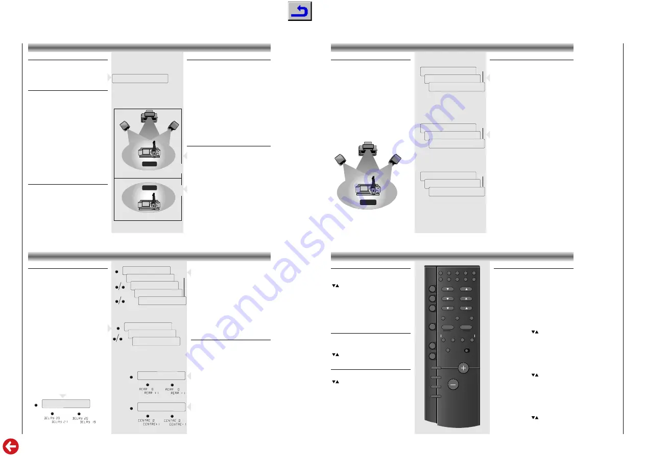
– For selecting the TV set (when connected to the
TV input).
y
TV
– To switch the TV to STAND BY.
– For selecting next or previous TV stations.
To control the following functions of the TV, make
sure that the HIFI - TV/VCR switch is in the
position TV/VCR
10-button keypad
for directly selecting stations .
TXT/TV
– For selecting teletext.
a
– For muting the speakers.
/–
– For controlling the volume of the
TV.
SAT
SAT
– For selecting the satellite receiver (when
connected to the TV input).
y
SAT
– To switch the satelite receiver to STAND
BY.
– For selecting next or previous satellite
programmes.
VCR
VCR
– For selecting the video recorder (when
connected to the VCR input).
– For selecting next or previous VCR stations.
To control the following functions of the video
recorder, make sure that the HIFI - TV/VCR switch
is in the position TV/VCR
B
– To start playback of the video recorder.
0
– To start recording.
9
– To switch the video recorder to STOP.
;
– To switch the video recorder to PAUSE.
Q R
– Fast winding of the tape in forward or
reverse direction.
P
P
P
P
P
P
SYSTEM REMOTE CONTROL
Operation of other brands
This remote control can be used to operate also
other brands of TV’s, Satellite receivers and Video
recorders. The codes for these other brands have
already been put in the memory.
For TV sets you can select 5 different presets, for
Satellite receivers 3 and for Video recorders 10
different presets.
How to select the right presets?
for TV sets
• Keep the TV button pressed and press one of the
number 1...5 of the numeric keys for approx. 6
seconds.
– On the display of your amplifier appears e.g.
TV 1
.
• To control if you have selected the right code,
press e.g. one of the
buttons.
– If your TV reacts to this command you have
selected the right preset.
– If your TV does not react, try to select another preset.
for Satellite receivers
• Keep the SAT button pressed and press number
1, 2 or 3 of the numeric keys for approx. 6
seconds.
– On the display of your amplifier appears e.g.
SAT 1
.
• To control if you have selected the right code,
press e.g. one of the
buttons.
– If your Satellite receiver reacts to this command
you have selected the right preset.
– If your Satellite receiver does not react, try to
select another preset.
for Video recorders
• Keep the VCR button pressed and press one of
the numeric keys (1...0) for approx. 6 seconds.
– On the display of your amplifier appears e.g.
VCR 1
.
• To control if you have selected the right code,
press e.g. one of the
buttons.
– If your VCR reacts to this command you have
selected the right preset.
– If your VCR does not react, try to select another preset.
P
P
P
P
P
P


