background image

16

English (US)

9. Technical data

9.1 Operating conditions

9.1.1 Flow rate

9.1.2 Temperatures

Thermal protection

9.1.3 Pumped liquid requirements

9.1.4 Inlet level and installation depth

9.2 Electrical data

9.2.1 Power supply

9.2.2 Insulation class

9.2.3 Capacitors

Pump type

 Max. head

[ft (m)]

Max. flow rate 

[gpm (m

3

/h)]

CC 5

16 (5)

26.7 (6)

CC 7

22 (7)

38.3 (10)

CC 9

29 (9)

58.3 (14)

Using the horizontal outlet may cause 
a 5 % drop in performance.

Maximum ambient 
temperature

104 °F (40 °C) 

Liquid temperature

32 to 104 °F (0 to 40 °C)

Operating 
temperature

32 to 104 °F (0 to 40 °C)

Storage 
temperature

14 to 122 °F 
(-10 to +50 °C)

Pump type

Winding temperature cut-out

CC 5

320 °F (160 °C)

CC 7

320 °F (160 °C)

CC 9

284 °F (140 °C)

At intervals of at least 30 minutes, the 
pump is allowed to run at maximum 
158 °F (70 °C) for periods not 
exceeding two minutes.

Do not use the thermal protection to 
control pump operation. If the pump is 
to be installed permanently in 
conditions with varying water level, 
install a pump with a float switch.

Pumped liquid

Rainwater and grey 
wastewater without long fibers

pH range

4-9 pH 

Maximum 
particle size

0.40 inch (10 mm)

Viscosity

Close to the viscosity of water 
or 1 cSt (1 mm

2

/s) at 68 °F 

(20 °C).

Pump 
type

Min. inlet level 

with inlet 

strainer

 [in. (mm)]

Min. inlet level 

without inlet 

strainer

[in. (mm)]

CC 5

0.79 (20)

0.12 (3)

CC 7

0.79 (20)

0.12 (3)

CC 9

0.79 (20)

0.12 (3)

Pump 
type

Max. installation depth

[ft (m)]

Cable length

[ft (m)]

CC 5
CC 7
CC 9

23 (7)

32.8 (10)

Pump type

Supply voltage [V]

CC 5
CC 7
CC 9

1 x 115 V, 60 Hz
1 x 230 V, 60 hz

60 Hz

CC 5

 CC 7

 CC 9

Voltage [V]

115 230 115 230 115 230

Current, I 1/1 [A] 2.6 1.2 3.4 1.6 6.7 3.1

Power, P1 [W]

270 270 370 370 730 730

Power factor,
cos 

φ

 1/1

0.95 0.97 0.95 0.98 0.92 0.95

Pump type

Cable type

Insulation 

class

CC 5, 230 V

H05RN-F 3G0.75

F

CC 7, 230 V

H07RN-F 3G1

F

CC 9, 230 V

H07RN-F 3G1

B

CC 5, 115 V
CC 7, 115 V
CC 9, 115 V

H07RN-F 3G1

B

Pump type

Capacitor

[

μ

F]

[Vc]

CC 5

4

450

CC 7

8

450

CC 9

8

450

Summary of Contents for Unilift CC 5

Page 1: ...GRUNDFOS INSTRUCTIONS Unilift CC 5 CC 7 CC 9 Installation and operating instructions US C ...

Page 2: ...4 3 Electrical connection 8 5 Starting up the product 9 5 1 Starting 9 5 2 Venting the product 10 5 3 Manual operation 10 5 4 Automatic operation with float switch 10 5 5 Pumping to a low water level 10 5 6 Thermal protection 10 6 Product introduction 11 6 1 Product description 11 6 2 Applications 12 6 3 Identification 13 7 Servicing the product 13 7 1 Maintaining the product 13 7 2 Cleaning the p...

Page 3: ... a service station must be sent freight prepaid documentation supporting the warranty claim and or a Return Material Authorization must be included if so instructed Grundfos will not be liable for any incidental or consequential damages losses or expenses arising from installation use or any other causes There are no express or implied warranties including merchantability or fitness for a particul...

Page 4: ...o the equipment Tips and advice that make the work easier CAUTION Crushing of feet Minor or moderate personal injury Wear safety shoes when handling the product Use the pump handle to move the pump Do not lift it by the power cable DANGER Electric shock Death or serious personal injury The installation electrical connection and maintenance of the product must be carried out by an authorized electr...

Page 5: ...pipe in a permanent installation DANGER Electric shock Death or serious personal injury Do not remove the power cable and strain relief Do not connect electrical conduit to the pump WARNING Electric shock Death or serious personal injury Connect the product only to a properly grounded receptacle We recommend that you connect the pump to an electrical circuit with a Ground Fault Circuit Interrupter...

Page 6: ...pump with a float switch Pump with a lever arm If supplied with a lever arm you can install the Unilift CC pump in a narrow pit The minimum dimensions for a narrow pit are 11 8 x 13 8 inches 300 x 350 mm Fig 5 Unilift CC with a lever arm 4 2 4 Foundation We recommend that you place the pump on a solid base See fig 6 Fig 6 Pump placed on a plate Ensure a minimum free cable length of 9 8 ft 3 m abov...

Page 7: ...lve is fixed when the adapter is fitted to the pump top outlet port Fig 8 Adapter position and non return valve function 4 2 7 Using the side outlet port If you want to use the side outlet port proceed as follows 1 Remove the non return valve and adapter from the top outlet port 2 Remove the side plug and screw it on the top outlet port 3 Fit the 90 bend adapter in the side outlet port Use thread ...

Page 8: ... and stop levels Pump type Min cable length L 3 9 in 100 mm Max cable length L 7 9 in 200 mm Start in mm Stop in mm Start in mm Stop in mm CC 5 13 8 350 4 5 115 15 75 400 2 2 55 CC 7 13 8 350 4 5 115 15 75 400 2 2 55 CC 9 15 2 385 5 9 150 17 435 3 5 90 Start Stop L TM03 0829 4209 Pump type Start and stop levels with a lever arm Start in mm Stop in mm CC 5 8 31 211 3 51 89 CC 7 8 31 211 3 51 89 CC ...

Page 9: ...rly Water is being pumped DANGER Electric shock Death or serious personal injury If the pump is used for cleaning or other maintenance of swimming pools garden ponds or similar places make sure that the power supply to the pump is routed through a ground fault circuit interrupter GFCI in accordance with state local governing codes and regulations DANGER Electric shock Death or serious personal inj...

Page 10: ...n the water level the float switch position and cable length 5 4 1 Forced operation of a pump with a float switch If the pump is used to drain water below the stop level of the float switch the float switch can be kept in a higher position by fixing it to the outlet pipe During forced operation the water level must be checked regularly to prevent dry running 5 5 Pumping to a low water level The pu...

Page 11: ...With a float switch installed the pump automatically starts and stops according to the level of the pumped liquid the pump can pump to a low water level during forced operation when the inlet strainer is removed Pump without a float switch Without a float switch the pump requires manual external start and stop the pump can pump to a low water level when the inlet strainer is removed Fig 15 Pump wi...

Page 12: ...not have any explosion proof approval See the Grundfos SL range DANGER Electric shock Death or serious personal injury Do not use the pumps in or at swimming pools garden ponds etc when there are persons in the water If the pump has been used for very dirty or chlorinated water flush the pump thoroughly with clean water after use Wear gloves and other suitable personal protective equipment in acco...

Page 13: ...he power supply before starting any work on the product Make sure that the power supply cannot be accidentally switched on DANGER Electric shock Death or serious personal injury If the power cable is damaged it must be replaced by the manufacturer his service agent or similarly qualified persons in order to avoid hazard CAUTION Biological hazard Minor or moderate personal injury Before carrying ou...

Page 14: ...ssible impurities between the motor and the pump housing Clean the impeller 8 Check that the impeller can rotate freely 9 Assemble the pump in reverse order of dismantling 7 3 Service kits The impeller assembly and power cable can be replaced The part numbers and the components included in the service kits are found in Grundfos Product Center at www grundfos us Alternatively contact your local Gru...

Page 15: ...by impurities Clean the pump See section 7 2 Cleaning the pump c The water level is too low when the pump is started The pump cannot self prime See section 9 Technical data Move the pump to a position with higher water level or add water until the pump starts sucking 3 The pump runs constantly but does not deliver the rated flow a The pump is partly blocked by impurities Clean the pump See section...

Page 16: ...trol pump operation If the pump is to be installed permanently in conditions with varying water level install a pump with a float switch Pumped liquid Rainwater and grey wastewater without long fibers pH range 4 9 pH Maximum particle size 0 40 inch 10 mm Viscosity Close to the viscosity of water or 1 cSt 1 mm2 s at 68 F 20 C Pump type Min inlet level with inlet strainer in mm Min inlet level witho...

Page 17: ...disposed of in an environmentally sound way 1 Use the public or private waste collection service 2 If this is not possible contact the nearest Grundfos company or service workshop See also end of life information at www grundfos com product recycling Maximum dry running time 1 minute Airborne noise emitted by pump 70 dB A Enclosure class IP68 ...

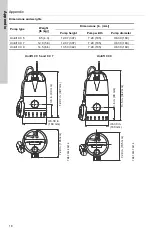
Page 18: ...lift CC 5 9 5 4 3 12 07 307 7 29 185 6 30 160 Unilift CC 7 12 8 5 8 12 07 307 7 29 185 6 30 160 Unilift CC 9 14 5 6 6 13 50 342 7 29 185 6 30 160 Unilift CC 5 and CC 7 Unilift CC 9 TM07 0538 0218 TM07 0537 0218 12 07 in 307 mm 6 30 in 160 mm 3 6 in 90 mm 7 29 in 185 mm 7 29 in 185 mm 6 30 in 160 mm 3 6 in 90 mm 13 5 in 342 mm ...

Page 19: ...7 3500 www grundfos us GRUNDFOS Canada 2941 Brighton Road Oakville Ontario L6H 6C9 Canada Phone 1 905 829 9533 Telefax 1 905 829 9512 www grundfos ca GRUNDFOS México Boulevard TLC No 15 Parque Industrial Stiva Aeropuerto C P 66600 Apodaca N L México Phone 011 52 81 8144 4000 Fax 011 52 81 8144 4010 www grundfos mx ...

Page 20: ...23391 www grundfos com The name Grundfos the Grundfos logo and be think innovate are registered trademarks owned by Grundfos Holding A S or Grundfos A S Denmark All rights reserved worldwide Copyright Grundfos Holding A S ...

Reviews: