background image

English (GB)

20

8.2 Pump controllers 

The following LC and LCD pump controllers are available for level 
control:
LC controllers are for one-pump-installations and LCD controllers 
are for two-pump installations.
• LC 107 and LCD 107 with air bells
• LC 108 and LCD 108 with float switches
• LC 110 and LCD 110 with electrodes.
In the following description, "level switches" can be air bells, float 
switches or electrodes, depending on the pump controller 
selected.
The 

LC

 controller is fitted with two or three level switches: 

One for start and the other for stop of pump. The third level 
switch, which is optional, is for high-level alarm. 
The 

LCD

 controller is fitted with three or four level switches: 

One for common stop and two for start of the pumps. The fourth 
level switch, which is optional, is for high-level alarm.
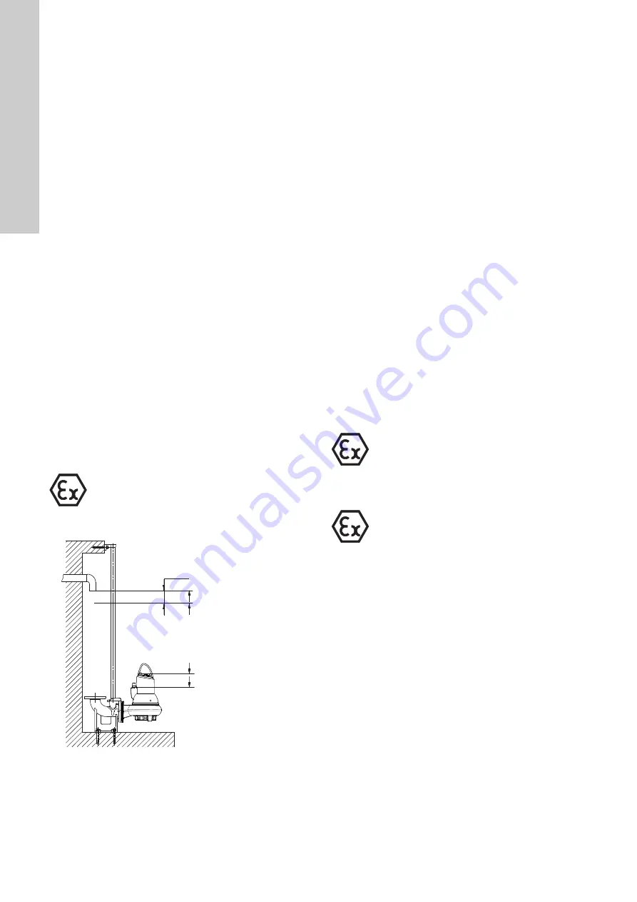
When installing the level switches, observe the following points:
• To prevent air intake and vibrations install the 

stop level 

switch

 in such a way that the pump is stopped before the 

liquid level is lowered below the top of the cable entry.

• In tanks with one pump, install the 

start level switch

 in such a 

way that the pump is started at the required level; however, 
the pump must always be started before the liquid level 
reaches the bottom inlet pipe to the tank.

• In tanks with two pumps, the 

start level switch

 for pump 2 

must start the pump before the liquid level reaches the bottom 
inlet pipe to the tank, and the start level switch for pump 1 
must start this pump correspondingly earlier.

• If installed, always install the 

high-level alarm switch 

about 

10 cm above the start level switch; however, the alarm must 
always be given before the liquid level reaches the bottom 
inlet pipe to the tank.

For further information, see the installation and operating 
instructions for the pump controller selected.

Fig. 10

Start and stop levels

Make sure that the effective volume of the tank does not become 
so low that the number of starts per hour exceeds the maximum 
permissible number. See section 

9.2 Operating modes

.

8.3 Thermal switch, Pt1000 and PTC thermistor

All SL1 and SLV pumps have thermal protection incorporated in 
the stator windings.

Pumps without sensor

Pumps without sensor have a thermal switch or a PTC thermistor. 
Via the pump controller safety circuit, the thermal switch will stop 
the pump by breaking the circuit in case of overtemperature 
(approx. 150 °C). The thermal switch will reclose the circuit after 
cooling. For pumps equipped with a PTC thermistor, connect the 
thermistor to either the PTC relay or the I/O module to break the 
circuit at 150 °C.
The maximum operating current of the thermal switch is 0.5 A at 
500 VAC and cos 

φ

 0.6. The switch must be able to break a coil in 

the supply circuit.

Pumps with sensor

Pumps with sensor have either a thermal switch and a Pt1000 
sensor or a PTC thermistor in the windings, depending on the 
installation site.
Via the pump controller safety circuit, the thermal switch or the 
thermistor will stop the pump by breaking the circuit in case of 
overtemperature (approx. 150 °C). The thermal switch or the 
thermistor will reclose the circuit after cooling. 
The maximum operating current of both the Pt1000 and the 
thermistor is 1 mA at 24 VDC.

Non-explosion-proof pumps

When closing the circuit after cooling, the thermal protection can 
restart the pump automatically via the controller. Pumps from 
4 kW and up sold in Australia/New Zealand are fitted with a PTC 
thermistor.

Explosion-proof pumps

Warning

Float switches used in potentially explosive 
environments must be approved for this 
application. They must be connected to the 
Grundfos LC, LCD 108 pump controller via the 
intrinsically safe LC-Ex4 barrier to ensure a safe 
circuit.

TM

04 265

4 280

8

Start

Stop S1 operation

Alarm

Min. 10 cm

Stop S3 operation

Warning

The thermal protection of explosion-proof pumps 
must not restart the pump automatically. 
This ensures protection against overtemperature 
in potentially explosive environments. In pumps 
with sensor this is done by removing the short-
circuit between terminals R1 and R2 in the IO 111. 
See Electrical data in the IO 111 installation and 
operating instructions.

Warning

The separate motor-protective circuit breaker/
control box must not be installed in potentially 
explosive environments.

Summary of Contents for SL1.100.100.40.4

Page 1: ...SL1 and SLV pumps 1 1 11 kW 50 Hz Installation and operating instructions GRUNDFOS INSTRUCTIONS...

Page 2: ...novit v kon je men ne 2 2 kW Pou it normy EN 60335 1 2002 EN 60335 2 41 2003 Sm rnice pro elektromagnetickou kompatibilitu EMC 2004 108 ES Pro verze se sn ma em jsou pou ity n sleduj c normy EN 55014...

Page 3: ...korral kasutatakse ka standardi EN 60079 18 2004 Kehtib ainult toodetele mis on m eldud kasutamiseks potentsiaalselt plahvatusohtlikus keskkonnas II 2G varustatud eraldi ATEX tunnustuse andmesildiga...

Page 4: ...tene norme EN 60079 0 2006 EN 60079 1 2007 EN 13463 1 2001 EN 13463 5 2003 Za verzije senzora tako er je kori ten sljede i standard EN 60079 18 2004 Odnosi se samo na proizvode namijenjene uporabi u p...

Page 5: ...erd EN 60079 18 2004 Is alleen van toepassing op pompen welke gebruikt worden in een explosie gevaarlijke omgeving II 2G met een afzonderlijke ATEX goedkeurings plaatje en EG type onderzoekscertificaa...

Page 6: ...EMC 2004 108 CE Pentru variantele de senzor sunt utilizate urm toarele standarde EN 55014 1 2006 EN 55014 2 1997 Directiva referitoare la produsele pentru construc ii 89 106 CEE Standarde utilizate E...

Page 7: ...ustenmukaisuusvakuutus Me Grundfos vakuutamme omalla vastuullamme ett tuotteet SL1 ja SLV joita t m vakuutus koskee ovat EY n j senvaltioiden lains d nn n yhdenmukaistamiseen t ht vien Euroopan neuvos...

Page 8: ...c ortamlarda kullan lan rn II 2G uzere parcal olarak ATEX onay etiketi ve EC tip muayene sertifikas verilebilmektedir Ayr nt l bilgi i in bkz a a da bu EC uygunluk bildirgesi yaln zca Grundfos kurulu...

Page 9: ...16 8 Electrical connection 17 8 1 Wiring diagrams 18 8 2 Pump controllers 20 8 3 Thermal switch Pt1000 and PTC thermistor 20 8 4 WIO sensor water in oil sensor 21 8 5 Moisture switch 21 8 6 IO 111 21...

Page 10: ...r type 1 S tube impeller V SuperVortex impeller 2 5 Operating conditions The Grundfos SL1 and SLV pumps are suitable for the following operating situations S1 operation continuous operation the pump m...

Page 11: ...seal O rings oil and the cable entry 4 Identification 4 1 Nameplate The nameplate states the operating data and approvals applying to the pump The nameplate is fitted to the side of the motor housing...

Page 12: ...P2 10 kW 4 kW Blank A Sensor version Standard Sensor version Blank Ex Pump version Non explosion proof pump standard Explosion proof pump 2 4 Number of poles 2 pole 4 pole 50 Frequency 50 Hz 0B 0D 1D...

Page 13: ...Equipment category according to the ATEX directive Annex II point 2 2 defining the requirements applicable to the equipment in this category G Explosive atmosphere caused by gases or vapours Harmoniz...

Page 14: ...stible liquids Warning The classification of the installation site must be approved by the local fire fighting authorities in each individual case Special conditions for safe use of SL1 and SLV explos...

Page 15: ...uide rails on the auto coupling base unit and adjust the length of the rails accurately to the guide rail bracket at the top of the tank 5 Unscrew the provisionally fastened guide rail bracket Insert...

Page 16: ...side diameter of the hose matches that of the pump discharge port If a rigid pipe is used fit the union or coupling non return valve and isolating valve in the order mentioned when viewed from the pum...

Page 17: ...n additional level switch must be installed to ensure that the pump is stopped in case the stop level switch is not operating Warning Connect the pump to an external mains switch which ensures all pol...

Page 18: ...ch PTC thermistor moisture switch and water in oil sensor Yellow green Not used Pumps from 4 kW and up sold in Australia New Zealand are fitted with a PTC thermistor TM04 6885 0710 Yellow green Standa...

Page 19: ...Sensor version Thermal switch PTC thermistor moisture switch and water in oil sensor Pumps from 4 kW and up sold in Australia New Zealand are fitted with a PTC thermistor TM04 6887 0710 Yellow green S...

Page 20: ...l switch Pt1000 and PTC thermistor All SL1 and SLV pumps have thermal protection incorporated in the stator windings Pumps without sensor Pumps without sensor have a thermal switch or a PTC thermistor...

Page 21: ...rs the IO 111 forms a galvanic separation between the motor voltage in the pump and the controller connected IO 111 can distinguish between two categories of fault Alarm The pump stops The fault is se...

Page 22: ...24 VDC 10 10 Input current Min 0 5 A max 8 A Power input Max 5 W Ambient temperature 25 C to 65 C Enclosure class IP20 Warning The IO 113 must not be used for purposes other than those specified above...

Page 23: ...tic noise 9 Start up 9 1 General start up procedure This procedure applies to new installations as well as after service inspections if start up takes place some time after the pump was placed in the...

Page 24: ...ion Check the direction of rotation before starting up the pump An arrow on the motor housing indicates the correct direction of rotation Correct direction of rotation is clockwise when viewed from ab...

Page 25: ...been replaced the oil must be changed Draining of oil 1 Place the pump on a plane surface with one oil screw pointing downwards 2 Place a suitable container approx 1 litre for instance made of transpa...

Page 26: ...2 3 Removing the seal ring and wear ring Procedure 1 Turn the pump housing upside down 2 Knock the seal ring pos 46 out of the pump housing using a punch Fig 19 Removing the seal ring 3 Clean the pump...

Page 27: ...in the pump housing 3 Knock the seal ring home in the pump housing using a punch or a wooden block Fig 21 Fitting the seal ring 4 Place the wear ring pos 49c on the impeller 5 Knock the wear ring hom...

Page 28: ...Stainless steel 97759207 97759208 97759202 97759203 97759209 97759204 97759205 49 Impeller 1 1 1 1 1 1 Pos Description SL1 50 SL1 50 SL1 50 SL1 80 SL1 80 SL1 80 SL1 80 2 pole 2 2 3 0 4 0 4 pole 1 5 2...

Page 29: ...r service no matter to whom it may be made must include details about the pumped liquid if the pump has been used for liquids which are injurious to health or toxic Before a pump is returned it must b...

Page 30: ...cations on the nameplate b Increased current consumption due to large voltage drop Measure the voltage between two motor phases Tolerance 10 6 Reestablish correct voltage supply c Impeller blocked by...

Page 31: ...n the EC Council Directive 2006 42 EC relating to machinery The supply cable resistance depends on the cable diameter Resistance per running metre of cable 1 5 mm2 0 012 Resistance per running metre o...

Page 32: ...witch 1 5 7 7 1 1 1 5 3 x 400 415 DOL Thermal switch 1 5 7 7 1 3 1 8 3 x 380 415 DOL Thermal switch 1 5 7 7 1 3 1 8 3 x 400 415 DOL Thermal switch 1 5 7 7 1 5 2 1 3 x 380 415 DOL Thermal switch 1 5 7...

Page 33: ...5 171 272 347 112 100 180 8 x M16 100 180 8 x 19 96 SL1 80 100 22 4 682 435 171 272 347 112 100 180 8 x M16 100 180 8 x 19 108 SL1 80 100 30 4 726 505 200 319 397 118 100 180 8 x M16 100 180 8 x 19 13...

Page 34: ...711 407 171 241 337 109 80 160 8 x M16 100 180 8 x 18 95 SLV 80 100 13 4 711 407 171 241 337 109 80 160 8 x M16 100 180 8 x 18 95 SLV 80 100 15 4 711 407 171 241 337 109 80 160 8 x M16 100 180 8 x 18...

Page 35: ...00 22 4 812 369 130 355 300 591 100 19 SL1 80 100 30 4 856 395 130 355 300 647 100 19 SL1 80 100 40 4 878 395 130 355 300 647 100 19 SL1 80 100 55 4 885 395 130 355 300 647 100 19 SL1 80 100 75 4 948...

Page 36: ...9 100 18 SLV 80 100 13 4 840 354 128 330 280 549 100 18 SLV 80 100 15 4 840 354 128 330 280 549 100 18 SLV 80 100 110 2 910 368 128 330 280 641 100 18 SLV 80 100 22 4 840 354 128 330 280 549 100 18 SL...

Page 37: ...270 878 652 489 110 2 0 830 148 0 220 413 180 100 4 x M16 SL1 80 100 22 4 260 110 270 878 652 489 110 2 0 830 148 0 220 413 180 100 4 x M16 SL1 80 100 30 4 260 110 270 948 722 536 110 2 0 848 122 0 2...

Page 38: ...80 4 x M16 SLV 80 100 11 4 260 110 270 850 624 458 110 2 0 842 131 0 220 413 160 80 4 x M16 SLV 80 100 13 4 260 110 270 850 624 458 110 2 0 842 131 0 220 413 160 80 4 x M16 SLV 80 100 15 4 260 110 270...

Page 39: ...Appendix 39 15 Exploded drawings SLV TM04 2777 2605...

Page 40: ...Appendix 40 SL1 TM04 2778 0904...

Page 41: ...41...

Page 42: ...22 Japan Phone 81 35 448 1391 Telefax 81 35 448 9619 Korea GRUNDFOS Pumps Korea Ltd 6th Floor Aju Building 679 5 Yeoksam dong Kangnam ku 135 916 Seoul Korea Phone 82 2 5317 600 Telefax 82 2 5633 725 L...

Page 43: ...nt to Article 11 5 Grundfos Holding A S Poul Due Jensens Vej 7 8850 Bjerringbro Denmark 5 NOT RELEVANT 6 System or systems of assessment and verification of constancy of performance of the constructio...

Page 44: ...bod 9 DK EU ydeevnedeklaration i henhold til bilag III af forordning EU nr 305 2011 Byggevareforordningen 1 Varetypens unikke identifikationskode EN 12050 1 eller EN 12050 2 SL1 50 2 Type parti eller...

Page 45: ...en Angewendete Normen EN 12050 1 2001 oder EN 12050 2 2000 SL12 50 10 Die Leistung des in Punkt 1 und 2 genannten Produkts entspricht der in Punkt 9 erkl rten Leistung EE EU toimivusdeklaratsioon on k...

Page 46: ...de aguas residuales que contengan materia fecal en cuya placa de caracter sticas figure la norma EN 12050 2 4 Nombre nombre comercial registrado o marca comercial registrada y domicilio de contacto de...

Page 47: ...a suite Normes utilis es EN 12050 1 2001 ou EN 12050 2 2000 SL1 50 10 Les performances du produit identifi aux points 1 et 2 sont conformes aux performances d clar es au point 9 HR Izjava EU o izjavi...

Page 48: ...ringbro Danimarca 5 NON RILEVANTE 6 Sistema o sistemi di valutazione e verifica della costanza delle prestazioni del prodotto da costruzione come definito sub all V Sistema 3 7 In caso di dichiarazion...

Page 49: ...n azonos tott term k teljes tm nye sszhangban van a 9 pontban megadott teljes tm nnyel NL Prestatieverklaring van EU in overeenstemming met Bijlage III van verordening EU nr 305 2011 Bouwproductenvero...

Page 50: ...50 do pompowania ciek w bez zawarto ci fekali w oznaczone na tabliczce znamionowej kodem EN 12050 2 4 Nazwa zastrze ona nazwa handlowa lub zastrze ony znak towarowy oraz adres kontaktowy producenta wy...

Page 51: ...50 10 O desempenho do produto identificado nos pontos 1 e 2 encontra se em conformidade com o desempenho declarado no ponto 9 RO Declara ie UE de performan n conformitate cu anexa III a Regulamentului...

Page 52: ...2 2000 SL1 50 10 Parametre v robku uveden v bodoch 1 a 2 s v zhode s deklarovan mi parametrami v bode 9 SI Izjava EU o delovanju v skladu z Dodatkom III Uredbe EU t 305 2011 uredba o gradbenih proizvo...

Page 53: ...N 12050 1 2001 ili EN 12050 2 2000 SL1 50 10 Performanse proizvoda identifikovanog u ta kama 1 i 2 u saglasnosti su s deklarisanim performansama u ta ki 9 FI EU suoritustasoilmoitus laadittu asetuksen...

Page 54: ...Y netmeli i Ek III e uygun olarak performans beyan n aat r n Y netmeli i 1 r n tipi zel tan mlama kodu EN 12050 1 veya EN 12050 2 SL1 50 2 Gereken ekil in aat r n n n Madde 11 4 e g re tan mlanmas na...

Page 55: ...U declaration of performance reference number 96771279 Tatab nya 15th May 2013 Jannek Uldal Christesen Manager GRUNDFOS Manufacturing Ltd B zavir g u 14 Ipari Park Tatab nya 2800 Hungary 98484577 0513...

Page 56: ...1789 The name Grundfos the Grundfos logo and be think innovate are registered trademarks owned by Grundfos Holding A S or Grundfos A S Denmark All rights reserved worldwide Copyright Grundfos Holding...

Reviews: