background image

English (GB)

14

18. Remove the flange mounting tool and nuts. The flange should 

stay in place.

19. Fit the screws (185) and nuts (208b). Cross-tighten the 

screws. Torque: 5-6 Nm.

20. Fit the gaskets (208a) and screws (208) in the two available 

holes of the flange.

21. Remove the pin and fit the last gasket (208a) and screw (208)
22. Lubricate the shaft ends and fit the seal rings (156 c and 

156d) or gamma rings (1159d and 159e). Use a punch.

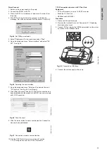
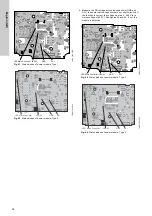
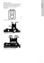
Fig. 29

Fitting the seal ring or gamma ring with a punch

23. Fit the parallel key (172a) on the drive-end of the shaft.
24. Check that the shaft can rotate freely.
25. Fit the fan and cover. See section 

7.11 Replacing the fan

.

26. Fit the terminal box. See section 

7.10 Replacing the stator 

housing

.

7.14 Replacing the IP66 gamma rings

1. Disconnect the power supply.
2. Remove the stator housing from the terminal box. See section 

7.10 Replacing the stator housing

.

3. Remove the fan. See section 

7.11 Replacing the fan

.

4. Remove the key from the shaft.
5. Remove the gamma rings (159d) from the shaft (172).
6. Lubricate the new gamma ring (159d) and fit it on the drive 

end of the shaft.

7. Lift the motor so that the non-drive end of the shaft rests on a 

solid, vibration-free surface.

8. Gently knock the ring home with the relevant punch. The 

distance between the flange (156b) and ring must be 0.8 to 
1.3 mm.

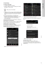
Fig. 30

Fitting the gamma ring on the drive end of the shaft

9. Support the motor so that it rests on the drive end of the shaft.
10. Lubricate the new gamma ring (159e) and fit it on the 

non-drive end of the shaft.

11. Gently knock the ring home with the relevant punch. The 

distance between the stator housing (150) and ring must be 
0.8 to 1.3 mm.

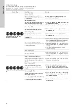
Fig. 31

Fitting the gamma ring on the non-drive end of the 
shaft

12. Fit the fan and cover. See section 

7.11 Replacing the fan

.

13. Fit the terminal box. See section 

7.10 Replacing the stator 

housing

.

T

M

06

 8

3

57

 16

17

The design of the punch ensures correct tolerances.

TM

06

 8

3

56

 23

16

T

M

06

 83

57

 23

16

Summary of Contents for MGE 100

Page 1: ...MGE and MLE model J Service instructions GRUNDFOS INSTRUCTIONS ...

Page 2: ...2 ...

Page 3: ...112 132 160 12 7 14 Replacing the IP66 gamma rings 14 7 15 Configuring the controller 15 8 Lubricating the bearings 18 9 Fault finding 19 9 1 General information 19 9 2 Fault indications 20 9 3 Functional module 22 9 4 Power module 25 9 5 Winding resistance 27 10 Exploded view 30 11 Disposal 31 Read this document before starting service work on the product Installation and service work must comply...

Page 4: ...roduct WARNING Biological hazard Death or serious personal injury Use personal protective equipment if there is a risk of getting into contact with the pumped liquid Observe local regulations WARNING Electric shock Death or serious personal injury Switch off the power supply and make sure that it cannot be accidentally switched on The power supply must be switched off for at least five minutes bef...

Page 5: ...ver 0 5 4 Nm F G Torque wrench 4 20 Nm H Bits kit 152 178 181 185 251d 268 273a 277a 286 287a 288a 289a Tx20 Tx25 Tx27 Tx30 Tx40 I Plastic hammer or press 156 1300 N axial force J Soft jaws For vice K Locking ring pliers internal ring 187 50 65 62 mm Locking ring pliers external ring 188 20 30 25 mm L Antistatic service kit 96884939 M Bearing heater 153 154 Special tools N Punch D20 156c 98394718 ...

Page 6: ...s 5 Press the battery home with a finger 6 Fit the terminal box cover See section 7 1 Replacing the terminal box cover 7 3 Fitting the antenna 1 Disconnect the power supply 2 Remove the terminal box cover See section 7 1 Replacing the terminal box cover 3 Remove the blanking plug 252b from the terminal box 4 Fit the union 291 in the terminal box 5 Lead the antenna into the union from above and tig...

Page 7: ... supply 2 Remove the terminal box cover See section 7 1 Replacing the terminal box cover 3 Remove the plug connection for the CIM module 4 Remove the cover 287 of the CIM module by pressing the locking tab fig 5 A and lifting the end of the cover fig 5 B Then lift the cover off the hooks fig 5 C Fig 5 Removing the cover of the CIM module 5 Remove the screw connecting the frame connection of the CI...

Page 8: ...on 7 4 Replacing the control panel 13 Fit the terminal box cover See section 7 1 Replacing the terminal box cover 7 7 Replacing the functional module 1 Disconnect the power supply 2 Remove the terminal box cover See section 7 1 Replacing the terminal box cover 3 Remove the control panel 290 from isolating cover 277 See section 7 4 Replacing the control panel 4 Remove the CIM module 502 from the is...

Page 9: ...ion cover 14 Fit the CIM module See section 7 5 Replacing the CIM module 15 Fit the control panel See section 7 4 Replacing the control panel 16 Fit the terminal box cover See section 7 1 Replacing the terminal box cover 17 Calibrate the functional module with the power module See section 7 15 Configuring the controller 7 9 Replacing the terminal box 1 Disconnect the power supply 2 Remove the term...

Page 10: ...a solid surface 6 Fit the fan cover on stator housing 150 and tighten screws 152 7 Fit the terminal box on the stator housing and cross tighten the screws 7 12 Replacing the bearings MGE 100 and below Dismantling 1 Disconnect the power supply 2 Remove the stator housing from the terminal box See section 7 10 Replacing the stator housing 3 Remove the fan See section 7 11 Replacing the fan 4 Remove ...

Page 11: ...Place the flange in the vice 7 Clean the bearing seat with a clean cloth and lubricate the bearing seat with anti fretting paste 8 Fit the rotor in the flange Fig 19 Fitting the rotor in the flange 9 Fit the locking ring 187 so that the bearing is held by the flange Fig 20 Fitting the locking ring for the bearing 10 Clean the bearing journal in the non drive end with a clean cloth 11 Heat the bear...

Page 12: ...ing from the terminal box See section 7 10 Replacing the stator housing 3 Remove the fan See section 7 11 Replacing the fan 4 Remove the parallel key 172a from the drive end of the shaft 5 Remove the gamma rings 159d and 159e or the seal rings 156c and 156d from the drive end and non drive end of the shaft 6 Remove the screws 206 from the non drive end flange 156a 7 Remove the non drive end flange...

Page 13: ...26 Lubricating the bearing 11 Fit the bearing cover 155 12 Heat the new bearing 153 to a temperature between 90 and 110 C 13 Fit the heated bearing 153 on the shaft 172 14 Fit the locking ring 188 15 Fitting the locking ring 16 Fit the drive end flange 156b Use a thin pin to align the holes of the bearing plates 155 with the holes of the flange Fig 27 Aligning flange bearing cover and stator housi...

Page 14: ...sing 3 Remove the fan See section 7 11 Replacing the fan 4 Remove the key from the shaft 5 Remove the gamma rings 159d from the shaft 172 6 Lubricate the new gamma ring 159d and fit it on the drive end of the shaft 7 Lift the motor so that the non drive end of the shaft rests on a solid vibration free surface 8 Gently knock the ring home with the relevant punch The distance between the flange 156b...

Page 15: ...itch on the power supply to the pump 2 Connect MI 301 to the PC 3 Start PC Tool The first time the program is started the message No COM port selected will be shown Click OK Fig 33 No COM port selected 4 Select Preferences in the main menu under Files 5 Open the dropdown menu Select interface and select MI 301 See fig 34 Fig 34 Selecting the user interface 6 Open the dropdown menu Select port and ...

Page 16: ... Click Apply 8 Click Radio Scan See fig 39 Wait until connection has been established to the products the MI 301 can communicate with 10 20 seconds Fig 39 Radio Scan 9 Mark the pump to be connected and click Connect See figures 40 and 41 Fig 40 Selection of unit Fig 41 Establish connection to the pump 10 Click the button for radio communication See fig 42 Status in PC Tool will change to Connected...

Page 17: ...ablished to the products the MI 301 can communicate with 10 20 seconds Fig 46 Direct Connect 9 Click the motor button for radio communication Connection has now been established Fig 47 Connection via radio communication 10 Find the GSC file for the motor by means of section 7 15 3 Configuration with the PC Tool E products 7 15 2 Connection to motor via PC Tool Link Equipment PC Tool E products ver...

Page 18: ...technician It is possible to relubricate the bearings five times according to the preset interval When the preset interval has been reached after the fifth relubrication a warning will be given to replace the bearings In the case of seasonal operation motor is idle for more than six months of the year we recommend that you lubricate the motor bearings when you take it out of operation It is import...

Page 19: ...ndications via Grundfos Eye See the indication of motor status by means of Grundfos Eye and the contact positions of signal relays in the installation and operating instructions for the MGE motor Fault indications via Grundfos GO Remote See the description of the Grundfos GO Remote control panel and possibilities of communication in the installation and operating instructions for the MGE motor Fig...

Page 20: ... thus the pump performance a Check that the viscosity and temperature of the pump liquid is within the limits for the pump If not change the properties of the liquid b Dismantle the pump and remove any foreign matter or impurities preventing the pump from rotating c If none of the above causes are present replace the pump Blocked pump 51 The pump is blocked a Dismantle the pump and remove any fore...

Page 21: ...mal range a Check that the sensor resistance corresponds to approximately 100 or 1000 ohm If not replace the sensor b Check the sensor cable for damage c Check the cable connection at the pump and at the sensor Correct the connection if required d Replace the sensor Supply fault 5 V 161 Fault in the output voltage to sensor or potentiometer a Check the output voltage and wire to sensor or potentio...

Page 22: ...nal injury Do not touch the terminals of the power module as they are still live Do not touch the relay RL1 as it may still be live Measuring equipment must be free of static electricity or have same potential as the motor before being used for measurement without isolation cover Status Fault Permanently on The microprocessor is frozen The functional module is defective See section 7 7 Replacing t...

Page 23: ...eck if the voltage between the reference point and the other measuring points is okay The voltage values apply to an operating motor Fig 54 Measuring voltage on the functional module To measure the voltage listed in the table below you must use the same reference point ref seen on the figure above Measure the DC voltage from e g ref to 1 The measure should be between 14 5 V and 15 7 V Replace the ...

Page 24: ... the values are not identical the module is defective Digital input DI See the settings of the input in PC Tool Connect the digital input to frame GND by means of an ammeter The value measured must now be approximately 12 mA Check that PC Tool shows a corresponding value Fig 58 Testing the digital input Digital output DO open collector OC See the settings of the output in PC Tool Measure the outpu...

Page 25: ...e the problem replace the power module See section 7 8 Replacing the power module LED Micro controller is off The power module is defective See section 7 8 Replacing the power module The LED Micro controller is flashing 180 times minute and the LED 5V is permanently on The power module is functional The LED 5V is off The power module is defective See section 7 8 Replacing the power module The LED ...

Page 26: ...the function is correct the voltage must be 566 V at a mains voltage of 400 V See figures 63 and 64 If not the module is defective Fig 63 Status diodes of power module Type 3 Fig 64 Status diodes of power module Type 4 TM06 7194 3016 TM06 7195 3016 LED Micro Controller LED 5V GND DC GND DC LED Micro Controller LED 5V TM06 7194 3016 TM06 7195 3016 LED Micro Controller LED 5V GND DC GND DC LED Micro...

Page 27: ...e below It may be necessary to let the motor cool off if it has been running or if it was stopped because of short circuit or overload Wiring diagram Fig 65 Wiring diagram Fig 66 Measure the winding resistance Fig 67 Measure the winding resistance TM05 7025 0413 TM06 7722 3916 TM06 7723 3916 U1 V1 W1 U1 Blue V1 Red W1 Yellow U1 Blue V1 Red W1 Yellow U1 Blue W2 Black V1 Red U2 Green W1 Yellow V2 Wh...

Page 28: ... 3 5 4 1 3 8 4 4 1 1 1 5 1 6 1 8 1 8 2 1 1 9 2 3 3 x 380 500 0 25 0 33 10 4 12 2 12 14 1 12 8 15 1 1 1 1 5 5 3 6 3 6 2 7 2 6 6 7 7 3400 4000 3 x 200 240 1 1 1 5 1 08 1 24 1 25 1 43 1 33 1 53 4000 5900 1 x 200 240 0 75 1 1 5 1 7 1 7 2 1 8 2 1 1 1 1 5 1 5 1 7 1 7 2 1 8 2 1 3 x 380 500 0 75 1 4 6 5 4 5 3 6 2 5 7 6 7 1 1 1 5 4 6 5 4 5 3 6 2 5 7 6 7 MGE 90 MLE 90 1500 2000 3 x 380 500 1 1 1 5 8 9 10 5 ...

Page 29: ...5900 3 x 380 500 5 6 7 5 0 95 1 1 1 1 1 3 1 2 1 4 3 x 440 480 MGE 132 MLE 132 2000 2200 3 x 380 500 5 6 7 5 1 6 1 9 1 8 2 2 1 9 2 3 3 x 440 480 MGE 132 MLE 132 2000 2200 3 x 380 500 7 5 10 0 1 1 1 3 1 3 1 5 1 4 1 6 3 x 440 480 MGE 132 MLE 132 3000 4000 3 x 380 500 7 5 10 0 0 75 0 87 0 86 1 0 0 9 1 1 3 x 440 480 MGE 160 MLE 160 3000 4000 3 x 380 500 11 0 15 0 4 0 45 0 45 0 54 0 49 0 57 3 x 440 480 ...

Page 30: ...English GB 30 10 Exploded view Fig 68 MGE model J MGE 132 TM06 6857 2516 ...

Page 31: ...11 Disposal This product or parts of it must be disposed of in an environmentally sound way 1 Use the public or private waste collection service 2 If this is not possible contact the nearest Grundfos company or service workshop TM06 6928 2716 ...

Page 32: ...32 ...

Page 33: ...33 ...

Page 34: ...34 ...

Page 35: ...NDFOS Pumps Korea Ltd 6th Floor Aju Building 679 5 Yeoksam dong Kangnam ku 135 916 Seoul Korea Phone 82 2 5317 600 Telefax 82 2 5633 725 Latvia SIA GRUNDFOS Pumps Latvia Deglava biznesa centrs Augusta Deglava ielā 60 LV 1035 Rīga Tālr 371 714 9640 7 149 641 Fakss 371 914 9646 Lithuania GRUNDFOS Pumps UAB Smolensko g 6 LT 03201 Vilnius Tel 370 52 395 430 Fax 370 52 395 431 Malaysia GRUNDFOS Pumps S...

Page 36: ...isplayed in this material including but not limited to Grundfos the Grundfos logo and be think innovate are registered trademarks owned by The Grundfos Group All rights reserved 2019 Grundfos Holding A S all rights reserved www grundfos com ...

Reviews: