English (GB)
17
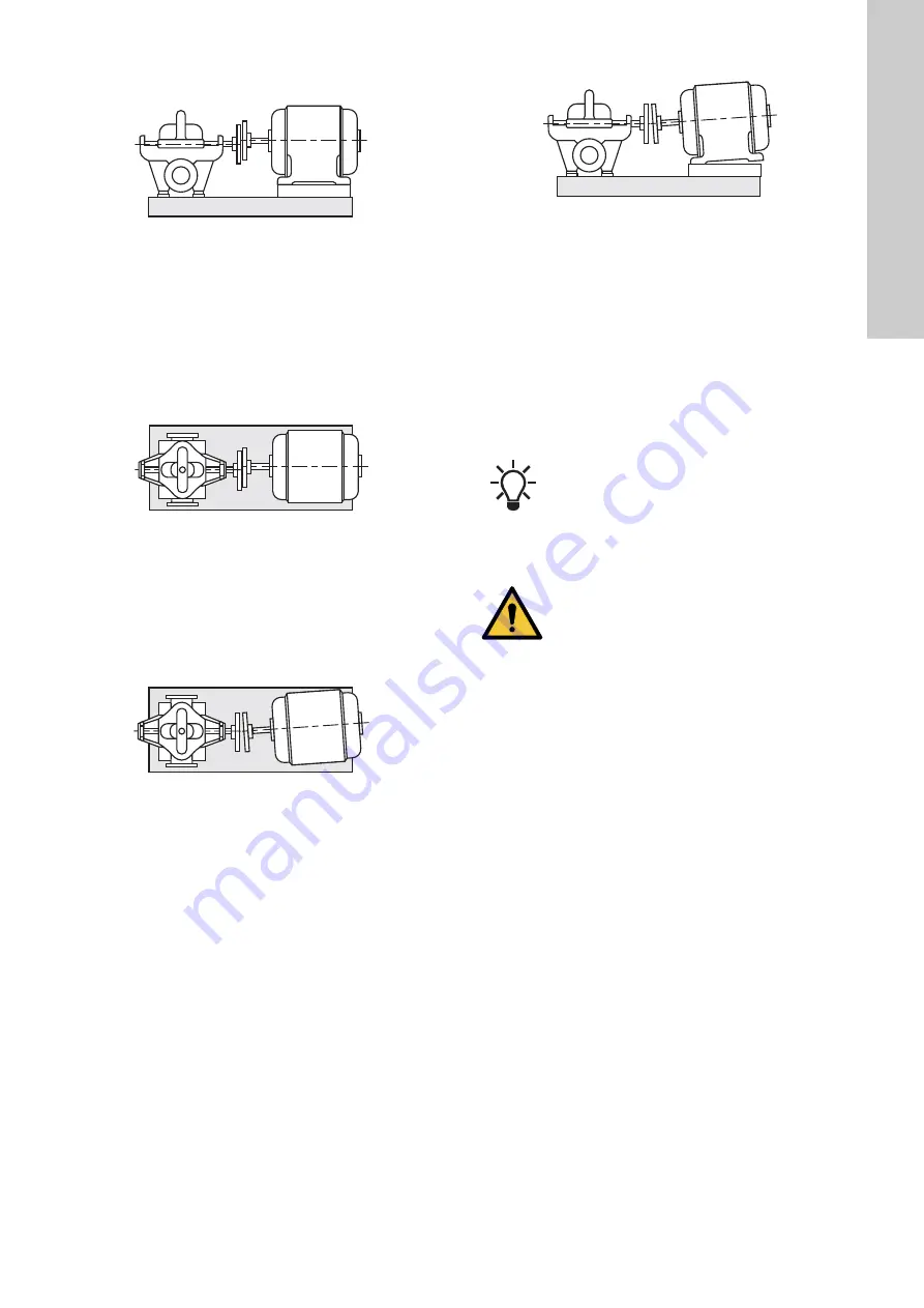
The coupling alignment procedure has four steps:
Parallel alignment - vertically
1. Mount the dial gauge (2) in position 0 ° (12 o'clock). See fig.
2. Make the index lines on the two coupling halves. See fig. 10.
3. Set the dial gauge pointer to zero, turn the motor and pump
shaft simultaneously until the dial gauge is in position 180 ° (6
o'clock) and check that the index lines are still in line.
4. Read the dial gauge (2). If the dial gauge shows a deflection
exceeding 0.2 mm, add or remove the shims under the motor
until the reading of the dial gauge is within the allowable
tolerance of 0.2 mm.
Parallel alignment - horizontally
1. Turn the motor and pump shaft to 270 ° (9 o'clock).
2. Set the dial gauge pointer to zero, turn the motor and pump
shaft to 90 ° (3 o'clock) and check that the index lines are still
in line.
3. Read the dial gauge. If the dial gauge shows a deflection
exceeding 0.2 mm, move the motor sideways until the reading
of the dial gauge is within the allowable tolerance of 0.2 mm.
4. Remove the dial gauge (2).
Angular alignment - horizontally
1. Mount the dial gauge (1) in position 90 ° (3 o'clock). See fig.
2. Make the index lines on the two coupling halves. See fig. 10.
3. Set the dial gauge pointer to zero, turn the motor and pump
shaft simultaneously until the dial gauge is in position 270 ° (9
o'clock) and check that the index lines are still in line.
4. Read the dial gauge (1). If the dial gauge shows a deflection
exceeding 0.2 mm, move the motor sideways until the
deflection is halved.
5. Set the dial gauge pointer to zero, turn the motor and pump
shaft simultaneously until the dial gauge is in position 90 ° (3
o'clock) and read the dial gauge (1) again.
6. Now the reading must be within the allowable tolerance of 0.2
mm. If not, repeat the procedure.
Angular alignment - vertically
1. Turn the motor and pump shaft until the dial gauge (1) is in
position 0 ° (12 o'clock).
2. Set the dial gauge pointer to zero, turn the motor and pump
shaft simultaneously until the dial gauge is in position 180 ° (6
o'clock) and check that the index lines are still in line.
3. Read the dial gauge (1). If the dial gauge shows a deflection
exceeding 0.2 mm, add or remove the shims under the motor
until the deflection is halved.
4. Set the dial gauge pointer to zero, turn the motor and pump
shaft simultaneously until the dial gauge is in position 0 ° (12
o'clock) and read the dial gauge (1) again.
5. Now the reading must be within the allowable tolerance of 0.2
mm. If not, repeat the procedure.
6. Remove the dial gauge (1).
Finish the alignment procedure by refitting and tightening the
coupling.
6. Taking the product out of operation
The following shutdown procedures apply to most normal
shutdowns. If the pump is to be inoperative for a long time, follow
the storage procedures in section
1. Always close the outlet valve or throttle valve before stopping
the pump. Close the valve slowly to prevent hydraulic shock,
but make sure that the pump does not run against a closed
valve for more than a few seconds.
2. Switch off the power supply to the motor.
6.1 Short-term shutdown
1. For overnight or temporary shutdown periods under
non-freezing conditions, the pump may remain filled with
liquid. Make sure the pump is fully primed before restarting.
2. For short or frequent shutdown periods at temperatures below
0 °C, keep the liquid moving within the pump housing and
insulate or heat the pump exterior to prevent freezing.
6.2 Long-term shutdown
For long shutdown periods or to isolate the pump for
maintenance, close the inlet and outlet valves. If no inlet valve is
fitted and the pump has positive inlet height, drain all liquid from
the inlet pipe to terminate the liquid flow into the pump inlet port.
If applicable, turn off any external source of cooling or lubricating
liquid to the stuffing boxes or shaft seals. Remove the plugs in the
pump drain and vent tappings, as required, and drain all liquid
from the pump housing. Remove the stuffing box glands and
packing rings, if applicable.
TM
03
2
939
49
05
T
M
03
29
41
49
05
TM0
3
294
2
4
9
0
5
T
M
03
29
40
49
05
The coupling tolerances may differ from coupling
make to coupling make. For the standard coupling,
the allowable tolerance is 0.2 mm. For other coupling
types, see the coupling data supplied with the pump.
WARNING
Personal injury
Death or serious personal injury
- To protect persons from rotating machine parts,
always install all guards after installation is
complete and before starting the pump.
Summary of Contents for LS 100-80-241
Page 1: ...LS Service instructions GRUNDFOS INSTRUCTIONS ...
Page 2: ...2 ...
Page 22: ...English GB 22 9 Sectional drawings 9 1 LS with sleeve construction type 1 TM03 9952 4707 ...
Page 30: ...English GB 30 Fig 18 Construction type 3 LS 100 80 241 XE TM03 9951 4317 ...
Page 34: ...English GB 34 Fig 25 Construction type 4 LS 300 200 489 LS 350 250 508 TM03 9942 4317 ...
Page 44: ...44 ...
Page 45: ...45 ...
Page 46: ...46 ...


