


English (GB)
14
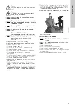
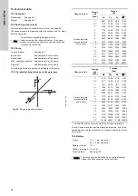
6.9.2 Fuel tank connection
If there is no connecting block, connect the fuel pipes as shown in
fig. 21 to the flow pipe (pos. A, from the manual fuel supply pump)
and the return pipe (pos. B, from the injection pump).
Fig. 21
Connecting the fuel pipes without connecting block.
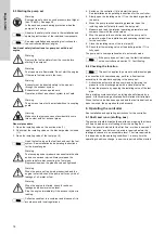
If there is a connecting block (see fig. 21, pos. A), connect both
fuel pipes to the connecting block. The connecting block is
marked "SUPPLY" for the incoming pipe and "RETURN" for the
return pipe.
Fig. 22
Connecting the fuel pipes to the connecting block
6.10 Separate control cabinet
6.10.1 Flex version
For the "Flex" version, the control cabinet is mounted onto the
separate fuel tank. In this case, place the controller as close to
the pump as possible and within view of the pump set.
The control cabinet must also be easily accessible.
6.10.2 Flex B version
For the "Flex B" version, the control cabinet is delivered on a
separate stand. In this case, place the controller as close to the
pump as possible and within view of the pump set. The control
cabinet must also be easily accessible.
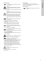
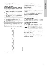
6.11 Mechanical fuel level indicator
Upon arrival of the fire set, the mechanical fuel level indicator is
not pre-installed. The fuel level indicator is stored in the base
frame.
Fig. 23
Fuel level indicator
Installing the fuel level indicator
1. Remove the plastic cap from the connection on the top of the
fuel tank.
2. Adjust the indicator disc on the display to equal 100 when the
weight is in top.
3. Install the mechanical fuel level indicator. Ensure that the
display is facing the same direction as the controller.
6.12 Fuel hand pump
The pump set is equipped with a fuel hand pump. See fig. 2.
Use the fuel hand pump to manually pump diesel fuel from
transportable containers into the fuel tank. The fuel hand pump is
designed for this purpose only. Fuel most not remain in the plastic
hoses. The plastic hoses are supplied together with the fuel hand
pump.
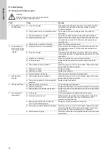
6.13 Leaklines
The Fire HSEF pump is equipped with leaklines. The leaklines
drains excessive water from the stuffing box. The leaklines must
be connected to drain. See fig. 24.
Fig. 24
Leakline
T
M
04
9
8
51
02
11
T
M
04
50
69
26
09
Note
See also installation and operating instructions for
the controller.
Caution
Warning
Make sure that water escaping from the pump or
pipework cannot damage the control cabinet.
The control cabinet is only intended to be installed
indoors and must not be exposed to direct sunlight.
Ensure sufficient ventilation for the components in
the control cabinet.
Caution
Install the fuel level indicator before filling the tank.
TM
06
1
1
9
6
1
914
T
M
06
24
92
43
14
Fuel level indicator
Leakline


