12
8.8 Piping
8.9 Recommended piping practices
•
Whenever possible, avoid fittings that cause high pressure
loss, such as elbows or branch tees directly on either side of
the pump.
•
The piping should be adequately supported to reduce thermal
and mechanical stress on the pump.
•
Good installation practice recommends the system be
thoroughly cleaned and flushed of all foreign materials and
sediment prior to pump installation.
•
Furthermore, the pump should never be installed at the lowest
point of the system due to the natural accumulation of dirt and
sediment. If there is excessive sediment or suspended
particles present, it is advisable to use a strainer or filter.
•
Grundfos recommends that pressure gauges be installed on
suction and discharge volute ports or in pipes to check pump
and system performance.
8.10 Check valves
A check valve may be required on the discharge side of the pump
to prevent the pump’s inlet pressure from being exceeded. For
example, if a pump with no check valve is stopped because there
is no demand on the system (all valves are closed), the high
system pressure on the discharge side of the pump will "find" its
way back to the inlet of the pump. If the system pressure is
greater than the pump’s maximum inlet pressure rating, the limits
of the pump will be exceeded and a check valve needs to be fitted
on the discharge side of the pump to prevent this condition.
8.11 Bypass
A bypass should be installed in the discharge pipe if there is
any risk that the pump may operate against a closed valve in
the discharge pipe. Flow through the pump is required to ensure
that adequate cooling and lubrication of the pump is maintained.
See fig. 5 for minimum flow rates. Elbows should be a minimum
of 12 inches from the discharge port to prevent erosion.
8.12 Assembly of motor and pump end
Proceed as follows:
1. Remove the key from the motor shaft, if present, and discard.
2. Thoroughly clean the surfaces of the motor and pump end
mounting flange. The motor and shaft must be clean of all oil/
grease and other contaminants where the coupling attaches.
3. Set the motor on the pump end.
4. Place the terminal box in the desired position by rotating the
motor so that the motor feet are in line with the pump foot.
5. Insert the mounting bolts. Then tighten diagonally and evenly:
– for 3/8" bolts (1/2 to 2 hp), tighten to 17 ft- b
– for 1/2" bolts (3 to 40 hp), tighten to 30 ft-lb
– for 5/8" bolts (50 to 60 hp), tighten to 59 ft-lb.
6.
CR, CRN 1s, 1, 3 and 5 H
Insert the shaft pin into the shaft hole.
Fit the coupling halves onto the shaft and shaft pin.
Fit the coupling screws and leave loose.
Check that the gaps on either side of the coupling are even
and that the motor shaft keyway is centered in the coupling
half.
Tighten the screws to the correct torque.
CR, CRN 10, 15 and 20 H
Insert the shaft pin into the shaft hole.
Insert the plastic shaft seal spacer beneath the shaft seal
collar.
Fit the coupling halves onto the shaft and shaft pin.
Fit the coupling screws and leave loose.
Check that the gaps on either side of the coupling are even
and that the motor shaft keyway is centered in the coupling
half.
Step
Action
1
TM
04
37
36
49
08
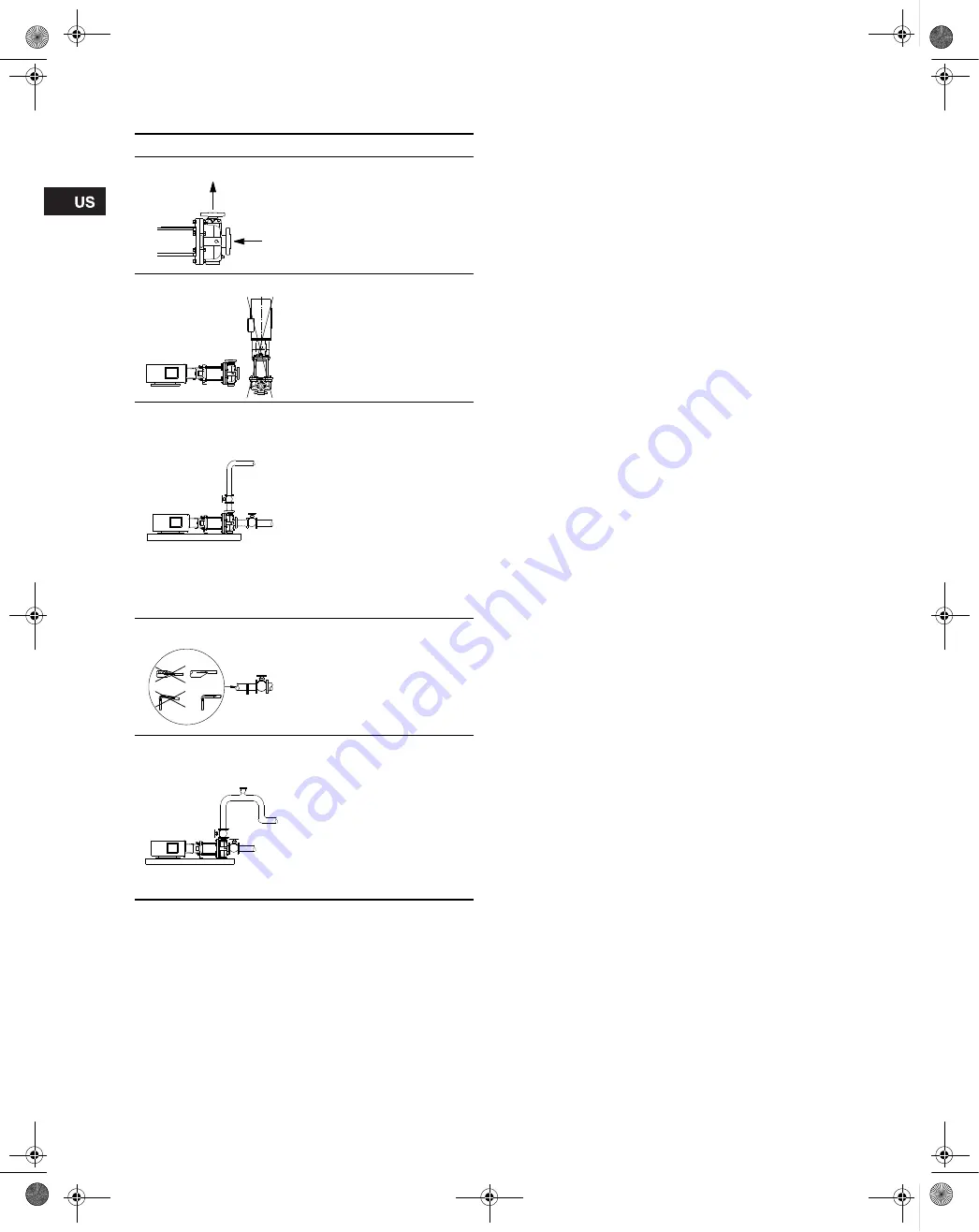
The arrows in the drawing show
the direction of flow of liquid
through the pump.
2
TM
04
37
37
49
08
The pump must be installed
horizontally.
Ensure that an adequate supply
of cool air reaches the motor
cooling fan.
3
T
M
04
37
38
49
0
8
To minimize possible noise from
the pump, it is advisable to fit
expansion joints on either side
of the pump. The foundation/
installation must be carried out
as described in section
8.2
.
Fit isolation valves on either
side of the pump to avoid
draining the system if the pump
needs to be removed for
cleaning, repair or replacement.
Always protect the pump
against backflow by means of a
check valve (foot valve).
4
TM0
2 0
1
14
38
00
Install the pipes so that air locks
are avoided, especially on the
suction side of the pump.
5
TM
04
37
39
49
08
Fit a vacuum valve close to the
pump if the installation has one
of these characteristics:
• The discharge pipe slopes
downwards away from the
pump.
• There is a risk of siphon
effect.
• Protection against backflow
of unclean liquids is needed.
Summary of Contents for CR-H
Page 1: ...CR H CRN H GRUNDFOS INSTRUCTIONS Installation and operating instructions ...
Page 2: ...2 ...
Page 62: ...62 ...


