Revised 02/09/2022
Page 3
42
’ Install Manual 9-W1 Solar Powered Attic Fan
outside.
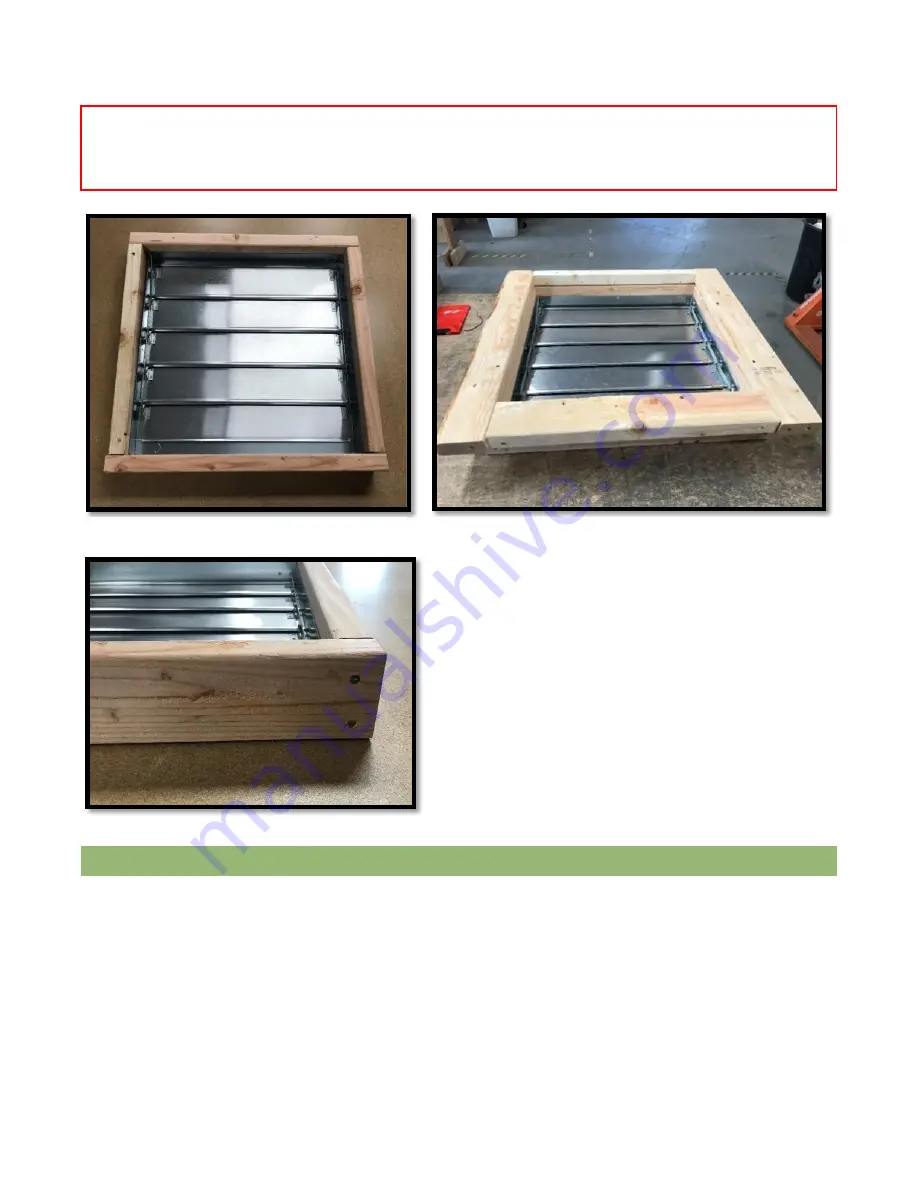
Using 3” screws, toe screw the frame together. Fasten the 2x4 connections with (2) 3” screws and the
2x2 connections with (1
) 3” screw. The shutter assembly is now complete (Figure 4).
Working from a ladder or scaffolding, complete the
installation of the fan by holding the shutter assembly
against the glazing with the louvers opening upwards, or
towards the fan
. The 2x2 should be against the “B” strut.
The wires from the fan should be between the frame and
glazing, so that connections can be made outside the
frame. Using the remaining (9) roofing screws, the person
outside will screw through the pre-drilled holes in the fan
flashing and into the shutter assembly. Apply caulk around
the fan flashing edge and over any exposed screw heads to
weatherproof your installation. Tape the edges of the fan
flashing with 2-1/2
” aircraft tape. Inside the dome, secure
the shutter assembly by screwing (3) 2-
1/2” screws through
the strut and into the 2x2/2x4 side of the frame.
While still on the ground, prepare the solar panel by installing the solar panel mounting brackets per the
instructions included with your specific Attic Breeze bracket kit. Begin by locating the power cable included with
your Attic Breeze solar attic fan. Make sure the power cable is long enough to reach the fan from where the
remote solar panel will be installed.
Using the included bootjack flashing piece, cut off the tip and slide the extra length of wire up through the
underside of the bootjack about 1-
2’ (Figure 6). Connect the end of the wire that you just slid through the bootjack
to the solar panel and seal the connection with electrical tape (Figure 7). Underneath where the panel will be
situated, drill a hole large enough to get the cable through (approximately 3/8”). Slide the other end of the wire
through the drilled hole, into the dome.
REMOTE MOUNTED SOLAR PANEL
3
rd
IMPORTANT ASPECT:
Test the shutter by lifting the louvers to ensure they open and close freely. You may need to bend the louver
arms to achieve this. You may also need to adjust the spring location.
Figure 4
Figure 3
Figure 5


