


27
28
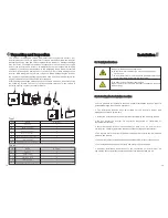
6.4.2 Connecting the PV Array (DC input)
DANGER
Danger to life due to lethal voltages!
Before connecting the PV array, ensure that the DC switch
and AC breaker are disconnect from the inverter. NEVER
connect or disconnect the DC connectors under load.
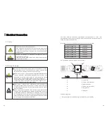
Make sure the maximum open circuit voltage (Voc) of each
PV string is less than 550Vdc.
Check the design of the PV plant. The Max. open circuit
voltage, which can occur at solar panels temperature of -
10
℃
, must not exceed the Max. input voltage of the
inverter.
Improper operation during the wiring process can cause
fatal injury to operator or unrecoverable damage to the
inverter. Only qualified personnel can perform the wiring
work.
WARNING
6.5 Using shinetool to set the information of the inverter
About the software of shinetool and the usage of it please download from the web:
www.ginverter.com/Download.aspx
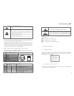
6.6 Grounding the inverter
The inverter must be connected to the AC grounding conductor of the power
distribution grid via the ground terminal (PE)
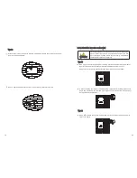
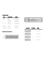
6.7 Selecting country by DIP switch
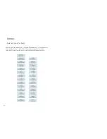
6.7.1 Location of the DIP switch
The DIP switch is located on the left of the RS232 interface at the bottom of the
inverter, as the figure below.
Because of the transformerless design, the DC positive
pole and DC negative pole of PV arrays are not permitted to
be grounded.
WARNING
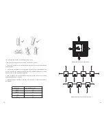
1. DC Connector 2. RS232 Interface 3. AC Connector
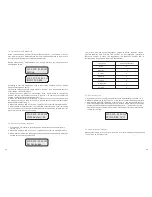
NOTE: Before selecting country, please turn off DC input and AC grid, then
unscrew the dam-board of the DIP switch by appropriate tool.
The internal structure of the DIP switch is as the following figure:
1
2
3
DIP
Swich
2 1
3
4
5


