OM-TDB/TDBC-CE 21
Parts List
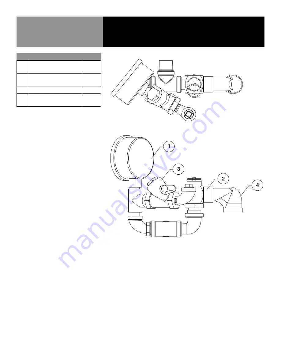
Key
Description
Part #
1
GAUGE, COMPOUND
PRESSURE W/DUAL
084208
2
VALVE, PRESSURE RELIEF 50
PSI, 1/2” NPT (PED)
141360
3
ASSY, WATER FILL SUB
137438
4
ELBOW, 3/4” NPT 90 DEG
STREET BRASS
010668
*Item not depicted/called out in drawing or photographs


