OPERATOR MANUAL
IMPORTANT INFORMATION, KEEP FOR OPERATOR
1055 Mendell Davis Drive, Jackson, MS 39272
888-994-7636, fax 888-864-7636
unifiedbrands.net
THIS MANUAL MUST BE RETAINED FOR FUTURE REFERENCE. READ,
UNDERSTAND AND FOLLOW THE INSTRUCTIONS AND WARNINGS
CONTAINED IN THIS MANUAL.
FOR YOUR SAFETY
Instructions to be followed in the event user smells
gas. This information shall be obtained by consulting your local gas
supplier. As a minimum, turn off the gas and call your gas company and
your authorized service agent. Evacuate all personnel from the area. Do
not store or use gasoline or other flammable vapors and liquids in the
vicinity of this or any other appliance
WARNING
Improper installation, adjustment, alteration, service or
maintenance can cause property damage, injury or death. Read the
installation, operating and maintenance instructions thoroughly before
installing or servicing this equipment.
NOTIFY CARRIER OF DAMAGE AT ONCE
It is the responsibility of the
consignee to inspect the container upon receipt of same and to determine
the possibility of any damage, including concealed damage. Unified
Brands suggests that if you are suspicious of damage to make a notation
on the delivery receipt. It will be the responsibility of the consignee to file
a claim with the carrier. We recommend that you do so at once.
Manufacture Service/Questions 888-994-7636.
PART NUMBER 174839, REV. E (03/19)
This manual provides information for:
ERGONOMIC TILTING BRAISING PAN
MODELS BPM-15/30/40G(C,A,C2T™) &
BPP-30/40G(C,A,C2T™) DOMESTIC
Information contained in this document is known to be current and accurate at the time of printing/creation. Unified Brands recommends
referencing our product line websites, unifiedbrands.net, for the most updated product information and specifications. © 2018 Unified Brands.
All Rights Reserved. Unified Brands is a wholly-owned subsidiary of Dover Corporation.
EQUIPMENT DESCRIPTION
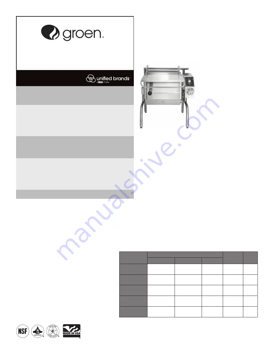
Groen gas-heated Tilting Braising Pans provide a stainless steel
pan equipped with patented heat transfer fins, burner/combustion
chamber, hand-operated or electric powered tilting mechanism,
electronic ignition, electronic controls, and hinged cover. The
appliance serves as braising pan, griddle, fry pan, oven, kettle,
bainmarie and food warmer/server, can be adapted for use as a non-
pressure steamer and can be used to stir-fry, reheat and saute foods.
The pan body is made from heavy-duty stainless steel welded into
one solid piece, with a polished interior and exterior. A pouring
lip is welded to the front wall. The cooking surface is a stainless
steel clad plate fitted with welded heat transfer fins which assure
uniform heat transfer over the entire surface. The gas burner/
combustion chamber supplies the heat.
An easily operated worm and gear mechanism tilts the pan and
provides precise control for pouring or dumping the contents of
the pan. This hand-wheel controlled mechanism is located in a
stainless steel console to the right of the pan body. For models with
electric power tilt, a switch operates an electric motor that starts
and stops the pan tilt smoothly. To assist cleaning, the pan body
can be tilted past the vertical position. When the pan is tilted, the
burners shut off automatically.
The electronic control provides automatic control of cooking temperature. Operating the
temperature dial on the front of the control console sets the pan temperature.
A heavy gauge, one-piece, stainless steel cover with a condensate drip shield on the rear edge
is standard on the Braising Pan. A fully enclosed, torsion bar type counterbalance provides
easy operation to open the cover and to maintain it open at any position. The cover opens to
the back and is hinged to the frame, so it moves independently of the pan body.
The braising pan is mounted on an open-leg frame fabricated from tubular stainless steel.
Model
PAN DIMENSIONS
Ignition
Tilt
Left to Right
Front to Rear
Depth
BPM-15GC/GA/
GC2T
18-1/8” (460mm) 28-1/4” (718mm)
8” (203mm)
Elec. Spark
Manual
BPM-30GC/GA/
GC2T
26-1/4” (667mm) 28-1/4” (718mm) 10” (254mm)
Elec. Spark
Manual
BPP-30GC/GA/
GC2T
26-1/4” (667mm) 28-1/4” (718mm) 10” (254mm)
Elec. Spark
Power
BPM-40GC/GA/
GC2T
35-3/4” (908mm) 28-1/4” (718mm) 10” (254mm)
Elec. Spark
Manual
BPP-40GC/GA/
GC2T
35-3/4” (908mm) 28-1/4” (718mm) 10” (254mm)
Elec. Spark
Power
REFERENCES
CANADIAN STANDARDS ASSOCIATION
8501 East Pleasant Valley Road
Cleveland, Ohio 44131
AMERICAN NATIONAL STANDARDS INSTITUTE
1403 Broadway
New York, New York 10018
CANADIAN GAS ASSOCIATION
55 Scarsdale Road
Don Mills, Ontario M3B 2 R3
NATIONAL FIRE PROTECTION ASSOCIATION
60 Battery March Park
Quincy, Massachusetts 02269
Z83-11 - Gas Foodservice Equipment
Z223.1 - National Fuel Gas Code
NFPA/54 - Installation of Gas Appliances
& Gas Piping
NFPA/70 - The National Electrical Code
NFPA/96 - Ventilating Hoods
NSF INTERNATIONAL
789 N. Dixboro Road
P.O. Box 130140
Ann Arbor, Michigan 48113-0140
UNDERWRITERS LABORATORIES, INC.
333 Pfingsten Road
Northbrook, Illinois 60062


