Grizzly T32720 Owner'S Manual Download Page 37

Model T32720 (Mfd. Since 06/21)

-35-

BUY PARTS ONLINE AT GRIZZLY.COM!

Scan QR code to visit our Parts Store.
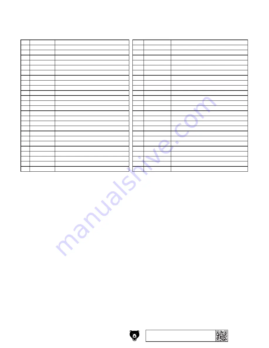
REF PART #

DESCRIPTION

REF PART #

DESCRIPTION

1

PT32720001

HEX NUT M12-1.75

27

PT32720027

ADJUSTMENT NUT M12-1.75 KN

2

PT32720002

FLAT WASHER 12MM

28

PT32720028

TOOL REST

3

PT32720003

GRINDING WHEEL TYPE-5 10 X 2-1/2 X 1/2

29

PT32720029

MOTOR TENSION NUT M8-1.25

4

PT32720004

ARBOR BUSHING

30

PT32720030

ROLL PIN 5 X 25

5

PT32720005

MACHINE HOUSING

31

PT32720031

MOTOR TENSION CAP

6

PT32720006

GRINDING WHEEL SPINDLE

32

PT32720032

CIRCUIT BOARD CR431V7

7

PT32720007

DRIVE WHEEL

33

PT32720033

KNOB BOLT M6-1 X 22, 6-LOBE, D30

8

PT32720008

DRIVE WHEEL TIRE

34

PT32720034

STRAIN RELIEF TYPE-1 1/2"

9

PT32720009

STROPPING WHEEL

35

PT32720035

STRAIGHT EDGE SHARPENING JIG

10

PT32720010

FLAT WASHER 8MM

35-1

PT32720035-1

RUBBER BUSHING

11

PT32720011

KNOB M8-1.25, 9-LOBE, D50

35-2

PT32720035-2

CONICAL COMP SPRING 0.8 X 8 X 13, 13OD

12

PT32720012

SWITCH BOX

35-3

PT32720035-3

CLAMP PLATE

13

PT32720013

ON/OFF SWITCH KEDU HY18

35-4

PT32720035-4

FLAT WASHER 6MM

14

PT32720014

CONTROL PANEL

35-5

PT32720035-5

KNOB BOLT M6-1 X 20, 6-LOBE, D30

15

PT32720015

TAP SCREW M4.2 X 16

35-6

PT32720035-6

BASE PLATE

16

PT32720016

STRAIN RELIEF TYPE-3 PG9

36

PT32720036

HEX NUT M8-1.25 THIN

17

PT32720017

RUBBER FOOT

37

PT32720037

FLAT WASHER 12MM

18

PT32720018

POWER CORD 18G 3W 78" 5-15P

38

PT32720038

ANGLE GUIDE

19

PT32720019

MOTOR 80W 120V 1-PH

39

PT32720039

CRIMP CONNECTOR 7.6 X 17.5MM

20

PT32720020

MOTOR PIVOT SHAFT

40

PT32720040

TAP SCREW M4.2 X 8

21

PT32720021

E-CLIP 10MM

41

PT32720041

DRIVE WHEEL COVER

22

PT32720022

COMPRESSION SPRING 1.2 X 13.4 X 75

42

PT32720042

TAP SCREW M4 X 14

23

PT32720023

EXT RETAINING RING 10MM

43

PT32720043

VARIABLE-SPEED DIAL

24

PT32720024

WATER RESERVOIR

44

PT32720044

CARBON BRUSHES (PAIR)

25

PT32720025

KNOB BOLT M8-1.25 X 45, 9-LOBE, D35

45

PT32720045

BRUSH CAP

26

PT32720026

LOCK COLLAR

46

PT32720046

ABRASIVE STROPPING PASTE

Main Parts List

Summary of Contents for T32720

Page 1: ...NG NO PORTION OF THIS MANUAL MAY BE REPRODUCED IN ANY SHAPE OR FORM WITHOUT THE WRITTEN APPROVAL OF GRIZZLY INDUSTRIAL INC CS21901 PRINTED IN CHINA V1 08 21 MODEL T32720 10 VARIABLE SPEED WET SHARPENE...

Page 2: ...g grinding tool integrity and the usage of personal protective equipment The manufacturer will not be held liable for injury or property damage from negligence improper training machine modifications...

Page 3: ...17 Selecting Grinding Wheel 18 Caring for Grinding Wheel 18 Inspecting Grinding Wheel 19 Adjusting Torque 19 Installing Tool Rest 20 Using Tool Jig 20 Setting Tool Angle 21 Filling Reservoir 21 Insta...

Page 4: ...ade every effort to be exact with the instruc tions specifications drawings and photographs in this manual Sometimes we make mistakes but our policy of continuous improvement also means that sometimes...

Page 5: ...other machinery with caution and respect Failure to do so could result in serious personal injury damage to equip ment or poor work results Like all machinery there is potential danger when operating...

Page 6: ...3 Control panel components J K A Tool Jig Lock Knob 1 of 2 Loosens to adjust tool jig position or angle and tightens to secure B Tool Rest Mounts in three different posi tions to support tool or tool...

Page 7: ...17 x 13 x 15 in Must Ship Upright No Electrical Power Requirement 120V Single Phase 60 Hz Full Load Current Rating 1 4A Minimum Circuit Size 15A Connection Type Plug Cord Power Cord Included Yes Powe...

Page 8: ...indle Thread Direction Right Hand Right Spindle Length 1 in Left Spindle Diameter 12mm Left Spindle Thread Pitch 1 75 TPI Left Spindle Thread Direction Left Hand Left Spindle Length 1 7 8 in Table Inf...

Page 9: ...d proof DANGEROUS ENVIRONMENTS Do not use machinery in areas that are wet cluttered or have poor lighting Operating machinery in these areas greatly increases the risk of accidents and injury MENTAL A...

Page 10: ...moving parts or flying debris Make sure they are properly installed undamaged and working correctly BEFORE operating machine FORCING MACHINERY Do not force machine It will do the job safer and better...

Page 11: ...and respira tor for type of grinding HAND WHEEL CONTACT Keep firm grip on workpiece and position hands safe distance away when grinding Anticipate when workpiece will heat up and cool it before it be...

Page 12: ...rsized circuit To reduce the risk of these hazards avoid over loading the machine during operation and make sure it is connected to a power supply circuit that meets the specified circuit requirements...

Page 13: ...ord size gets longer and the gauge size gets smaller higher gauge numbers indicate smaller sizes Any extension cord used with this machine must be in good condition and contain a ground wire and match...

Page 14: ...5 Inventory NOTICE If you cannot find an item on this list care fully check around inside the machine and packaging materials Often these items get lost in packaging materials while unpack ing or the...

Page 15: ...p contacts motor Cap Motor Direction to Push Motor Site Considerations Figure 6 Minimum working clearances Electrical Connection 15 18 Children and visitors may be seriously injured if unsuper vised a...

Page 16: ...gure 10 Assembly order for wheel installation 8 Mount grinding wheel components in order shown in Figure 10 Tighten arbor hex nut snugly but do not over tighten Over tightening can stress and crack wh...

Page 17: ...the switch disabling key disables the switch properly 3 Connect machine to power supply 4 Move ON OFF switch up to turn machine ON see Figure 12 5 Verify motor operation by slowly turning vari able s...

Page 18: ...kpiece inspects wheel to ensure there are no cracks or damage performs a ring test and installs wheel 3 Adjusts tool rest and tool jig as needed for operation 4 Secures workpiece in tool jig and adjus...

Page 19: ...Flexible Unstable Workpiece Grinding on the side or the ends of cable chain or round workpieces creates the hazard of workpiece twist or grab leading to entanglement with the wheel or shaft This hazar...

Page 20: ...thetic resins are used These are used to grind cemented carbide and ceramic materials Note There may be other numbers inserted that have meaning for a particular type of wheel Refer to the manufacture...

Page 21: ...wheel with a light non metallic device such as handle of a screwdriver or a wooden mallet Inspecting Grinding Wheel Figure 13 Tapping locations when performing a ring test STOP Rated 3500 RPM Make sur...

Page 22: ...eight 4 Tighten 2 lock knobs shown in Figure 15 to secure tool rest position Figure 15 Tool rest inserted in vertical mounting holes Tool rest should never be placed in vertical mounts for use with st...

Page 23: ...grinding with this machine can damage not only the wheel but also the tool or the blade you are grinding A dry wheel will soak up a lot of water in the first 15 minutes of saturation so be sure to add...

Page 24: ...st on a wheel before installing DO NOT use damaged wheels Installing Removing Grinding Wheel Wheels with varying grit are useful for different operations and workpiece materials DO NOT leave a wheel m...

Page 25: ...ot move while grinding Figure 22 Tool rest installed in vertical mounts Figure 23 Example of properly grinding against wheel rotation Grinding With Wheel Rotation 1 DISCONNECT MACHINE FROM POWER 2 Pos...

Page 26: ...l Mounts Tool Rest Figure 25 Example of properly grinding with wheel rotation 5 Rest workpiece against tool rest with sharp ened edge pointing away from you see Figure 25 6 Perform grinding operation...

Page 27: ...se the same dangers as a grinding wheel but replace it if it is torn or you notice a marked change in your sharpening results To replace stropping wheel 1 DISCONNECT MACHINE FROM POWER 2 Remove arbor...

Page 28: ...ector 7 T20503 Face Shield Window T20451 Kirova Clear Safety Glasses T20452 Kirova Anti Reflective S Glasses T20456 DAKURA Safety Glasses Black Clear T20451 T20452 T20502 T20503 T20456 Figure 30 Half...

Page 29: ...ely 220 T32796 Large Knife Sharpening Jig Mount this jig on the tool rest in the horizontal position to clamp knives 4 or longer for easy grinding T32798 Axe Sharpening Jig Grind axes against wheel ro...

Page 30: ...inding wheels can be easily damaged so it is important to store them properly Follow all wheel manufacturer storage instructions Always store grinding wheels in a location that is dry and pro tected f...

Page 31: ...ece material 3 Blown fuse on circuit board or circuit board at fault 4 Variable speed dial potentiometer at fault 5 Motor brushes worn out 6 Machine undersized for task 7 Motor overheated 8 Extension...

Page 32: ...t tool rest or use a holding device to firmly retain workpiece 3 Re dress wheel Page 28 Grinding wheel dulls quickly grit falls off 1 Operator using too much pressure 2 Wheel is too soft for material...

Page 33: ...shes are 1 2 long If your machine is used frequently we recom mend keeping an extra set of these replacement brushes on hand to avoid any downtime Items Needed Qty Dime or Penny 1 Pair of Motor Brushe...

Page 34: ...nt at the time of printing but may not match your machine If you find this to be the case use the wiring diagram inside the motor junction box CAPACITORS INVERTERS Some capacitors and power inverters...

Page 35: ...E 32 Neutral Hot Ground 120 VAC 5 15 Plug CONTROL PANEL BOX 6 3 1 4 2 5 ON OFF Switch KEDU HY18 Circuit Board CR431V7 Front Ground Back ACL Fuse 5A 250V L3 Potentiometer 120V MOTOR Wiring Diagram Figu...

Page 36: ...3 36 37 39 40 41 42 43 26 2 33 15 4 44 45 34 35 3 35 5 35 6 35 35 1 35 4 35 2 46 20 25 20 40 20 40 40 25 25 4 0 60 25 6 0 60 25 35 u 40 30 35 30 38 35 1 35 2 35 4 35 5 Main SECTION 9 PARTS We do our b...

Page 37: ...5 2 CONICAL COMP SPRING 0 8 X 8 X 13 13OD 12 PT32720012 SWITCH BOX 35 3 PT32720035 3 CLAMP PLATE 13 PT32720013 ON OFF SWITCH KEDU HY18 35 4 PT32720035 4 FLAT WASHER 6MM 14 PT32720014 CONTROL PANEL 35...

Page 38: ...roll up long sleeves and remove loose clothing jewelry or gloves to prevent getting caught in moving parts EYE LUNG INJURY HAZARD Always wear safety glasses and a respirator when using this machine W...

Page 39: ...rty or for incidental contingent special or consequential damages arising from the use of our products The manufacturers reserve the right to change specifications at any time because they constantly...

Page 40: ......

Reviews: