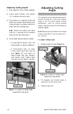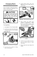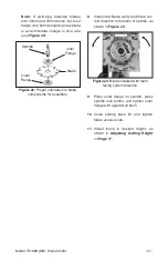
Figure 22. Proper orientation of blade
components for assembly.
Spindle
Blade
Outer
Flange
Inner
Flange
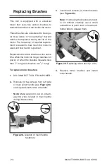
Figure 23. Blade installed with teeth
facing correct direction.
Model T31999 (Mfd. Since 02/20)
-21
-
Note:
If switching between blades
with 20mm and 22mm bores, flip inner
flange over before installing new blade
to accommodate change in bore size
(see
Figure 22).
8. Install new blade, verify teeth face cor-
rect direction for rotation of spindle, as
shown in
Figure 23.
9. Place outer flange on spindle, press
spindle lock button, and tighten outer
flange with spanner wrench.
10. Close sliding base lid and tighten
blade access knob.
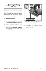
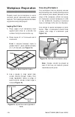
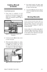
11. Install fence to desired height, as
shown in
Adjusting Cutting Height
on
Page 17.
Summary of Contents for T31999
Page 32: ......

