background image

G4030 6

1

2

" x 10" Metal-Cutting Bandsaw

-29-

Blade Change

Blades should be changed when they become 
dull, damaged, or when you are using materials 
that require a blade with a certain type or tooth 
count.

To change the blade on the bandsaw:

1. 

UNPLUG THE BANDSAW!

2.

  Raise the head of the bandsaw to the vertical 

position, close the Feed ON/OFF valve, and 
remove the wheel access cover.

3.

  Remove the blade guard.

4.

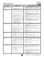
  Loosen the tension knob in 

Figure 38 

and 

slip the blade off of the wheels. This knob will 
be very tight and may be hard to loosen.

4.

  Install the new blade through both blade 

guide bearings, as shown in 

Figure 39,

 and 

around the bottom wheel. 

Figure 38. 

Tension knob and blade.

Figure 39. 

Installing blade.

5.

  Hold the blade around the bottom wheel with 

one hand and slip it around the top wheel with 
the other hand, keeping the blade between 
the blade guide bearings.


Note:


It is sometimes possible to flip the 

blade inside out, in which case the blade will 
be installed in the wrong direction. Check to 
make sure the blade teeth are facing toward 
the workpiece, as shown in 

Figure 40

,


after 

mounting to the bandsaw. Some blades will 
have a directional arrow as a guide.

6.

  When the blade is around both wheels, 

adjust the position so the back of the blade is 
against the shoulder of the wheels.

Figure 40. 

Blade cutting direction.

Summary of Contents for G4030

Page 1: ...NDSAW OWNER S MANUAL COPYRIGHT OCTOBER 2005 BY GRIZZLY INDUSTRIAL INC AUGUST 2011 TR WARNING NO PORTION OF THIS MANUAL MAY BE REPRODUCED IN ANY SHAPE OR FORM WITHOUT THE WRITTEN APPROVAL OF GRIZZLY IN...

Page 2: ...ERSONAL PROTECTIVE EQUIPMENT 4HE MANUFACTURER WILL NOT BE HELD LIABLE FOR INJURY OR PROPERTY DAMAGE FROM NEGLIGENCE IMPROPER TRAINING MACHINE MODIFICATIONS OR MISUSE 3OME DUST CREATED BY POWER SANDING...

Page 3: ...12 HZi Je HV Zin iZbh CZZYZY dg HZi Je JceVX c ckZcidgn VgYlVgZ GZXd c i dc 8 Vgi 8aZVc Je H iZ 8dch YZgVi dch 7gVX Zih KZgi XVa 6hhZbWan 8 e IgVn 9g e EVc IZhi Gjc GZXdbbZcYZY 6Y_jhibZcih SECTION 4...

Page 4: ...VYZ 8 Vc Z 7aVYZ IgVX c 7aVYZ IZch dc HfjVg c i Z 7aVYZ 7aVYZ j YZ 7ZVg c h aZXig XVa 8dbedcZcih L g c 9 V gVb EVgih 7gZV Ydlc EVgih 7gZV Ydlc EVgih 7gZV Ydlc EVgih A hi EVgih A hi EVgih A hi HV Zin A...

Page 5: ...YgVl c h VcY e did gVe h d i Z bVX cZ lZ jhZY l Zc lg i c i h bVcjVa dlZkZg hdbZi bZh lZ hi aa bV Z Vc dXXVh dcVa b hiV Z 6ahd dl c id djg eda Xn d Xdci cjdjh begdkZ bZci your machine may not exactly...

Page 6: ...Wood Slat Crate Content Machine Weight 289 lbs Length Width Height 19 x 45 x 43 in aZXig XVa Switch Automatic Shut Off Switch Voltage 110V Cord Length 5 1 2 ft Cord Gauge 16 gauge Plug Included Yes B...

Page 7: ...ody Construction Cast Iron Base Construction Pre formed Steel Wheel Cover Construction Pre formed Steel Paint Epoxy Di Zg Wheel Size 10 3 4 in Blade Guides Upper Ball Bearing Blade Guides Lower Ball B...

Page 8: ...Blade D Coolant Nozzle E 3 4 HP Motor F Wheels G Feed Rate ON OFF Valve H Bandsaw Cabinet Figure 1 Main view of machine features A B L N O G I F E D C I Workstop J ON OFF Switch for Coolant Nozzle K...

Page 9: ...CZkZg deZgViZ jcYZg i Z c ajZcXZ d Ygj h dg VaXd da l Zc i gZY dg l Zc Y higVXiZY OWNER S MANUAL GZVY VcY jcYZghiVcY i h dlcZg h bVcjVa 7 DG jh c bVX cZ JcigV cZY jhZgh XVc WZ hZg djhan jgi EYE PROTEC...

Page 10: ...bVWaZh dg c eddgan a i VgZVh ZZe ldg VgZV XaZVc Ygn VcY lZaa a iZY id b c b oZ g h d c_jgn Safety Instructions for Machinery APPROVED OPERATION JcigV cZY deZgVidgh XVc WZ hZg djhan jgi Wn bVX cZgn Dca...

Page 11: ...es for cracks and missing teeth before each use 2 HAND PLACEMENT Never position fin gers or thumbs in line with the cut Serious personal injury could occur 3 GUARDS Do not operate this bandsaw without...

Page 12: ...c deZgVi dc VcY bV Z hjgZ i h XdccZXiZY id V edlZg hjeean X gXj i i Vi bZZih i Z gZfj gZbZcih c i Z daadl c hZXi dc For your own safety and protection of property consult a qualified electrician if y...

Page 13: ...fj gZY eaj VcY gZXZeiVXaZ VcY bZZi i Z daadl c gZfj gZ bZcih Minimum Gauge Size 12 AWG Maximum Length Shorter is Better 50 ft Grounding Requirements c i Z ZkZci d XZgiV c ineZh d bVa jcXi dch dg WgZV...

Page 14: ...ious injury hazards to untrained users Read through this entire manu al to become familiar with the controls and opera tions before starting the machine Unpacking Set Up Safety SECTION 3 SET UP The Mo...

Page 15: ...G4030 61 2 x 10 Metal Cutting Bandsaw 13 Hardware Recognition Chart...

Page 16: ...oil to protect them from corrosion during ship ment Remove this protective coating with a sol vent cleaner or citrus based degreaser such as Grizzly s G7895 Degreaser To clean thoroughly some parts m...

Page 17: ...easily be set up for vertical cutting operations Components and Hardware Needed Qty Table 1 To assemble the bandsaw for vertical cut ting 1 If a piece of wood is clamped in the vise for shipping purpo...

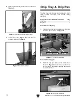
Page 18: ...s coolant over spray and cut offs during operation Components and Hardware Needed Qty Chip Tray 1 Drip Pan 1 To install the chip tray 1 Position the chip tray brackets over the cool ant basin lip as s...

Page 19: ...and correct before continuing If you need any help with your bandsaw call our Tech Support at 570 546 9663 Projectiles thrown from the machine could cause serious eye injury Wear safety glasses during...

Page 20: ...or equipment before WE STRONGLY REC OMMEND that you read books trade maga zines or get formal training before begin ning any projects Regardless of the con tent in this section Grizzly Industrial will...

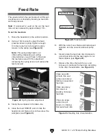
Page 21: ...ls Iron Hard Brass or Bronze 180 Aluminum and Plastics 235 Figure 16 Blade speed table Figure 17 Gear change lever 3 Pull up on the spring loaded lever and move the lever into your chosen speed see Fi...

Page 22: ...Always use a cutting fluid intend ed for magnesium The water in the solution will cause a magnesium chip fire This bandsaw has a built in cutting fluid system that extends the life of your bandsaw bla...

Page 23: ...ives For cutting cast iron cutting fluid is not rec ommended Remember Too much flow at the cutting fluid nozzle will make a mess and can make the work area unsafe and not enough fluid at the cut will...

Page 24: ...eed pressure Figure 24 Reading chip characteristics Chips are silvery thin small or powdery Increase feed rate Chips are large curled blue or brown or smoking Decrease feed rate Chips are width of too...

Page 25: ...ncrease your feed rate Chips that are burned indicate a need to reduce your feed rate Wait until the blade has completely stopped before removing the workpiece from the vise and avoid touching the cut...

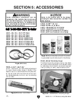
Page 26: ...be Tube is a stick lubricant designed to prevent heat buildup Apply it directly to the blade to improve overall blade life and productiv ity Can be used on ferrous and non ferrous met als Biodegradeab...

Page 27: ...edges Comes with two blades one for steel and aluminum and one for brass and cast iron T20501 Face Shield Crown Protector 4 T20502 Face Shield Crown Protector 7 T20503 Face Shield Window T20452 Kirov...

Page 28: ...Loose mounting bolts Damaged saw blade Worn or damaged wires Any other unsafe condition Clean after each use Monthly Check Lubricate vise screw Check gear box fluid level Annual Check Change gear box...

Page 29: ...d cor roded connections and repair replace as nec essary 8 Test repair replace Machine stalls or is underpowered 1 Wrong blade for the workpiece material 2 Wrong workpiece material 3 Feed rate cutting...

Page 30: ...spots welds or scale is on the material 5 The blade is twisted 6 The blade is slipping on the wheels 1 Refer to Changing Blade Speed on Page 19 and adjust as required 2 Refer to Blade Selection on Pa...

Page 31: ...hrough both blade guide bearings as shown in Figure 39 and around the bottom wheel Figure 38 Tension knob and blade Figure 39 Installing blade 5 Hold the blade around the bottom wheel with one hand an...

Page 32: ...oosening the set screw will move the blade away from the shoulder 7 Tension the blade 8 Put the gearbox in neutral by moving the gear change lever between two of the speed positions and spin the wheel...

Page 33: ...efficient cutting times Two major signs that you do not have proper blade tension are 1 the blade stalls in the cut and slips on the wheels and 2 the blade frequently breaks from being too tight To te...

Page 34: ...e bearings 1 UNPLUG THE BANDSAW 2 Position the bandsaw in the vertical position and close the feed rate ON OFF valve 3 Using a 12mm open end wrench loosen the hex nut that secures the bearing to the e...

Page 35: ...onents Figure 45 Motor wiring inside junction box Figure 48 G4030 Start capacitor Figure 46 Bandsaw ON OFF Switch wiring Figure 49 Pump ON OFF Switch wiring Figure 47 Submersible pump To Pump Capacito...

Page 36: ...jcXi dc 7dm Id Bdidg Bdidg EdlZg 8dgY 8VeVX idg L iZ GZY 7aVX gZZc gdjcY L gZ Cji 8dccZXi dc 8dccZXi dc HXgZl N 7 2 3 2 ISCONNECT POWER BEFORE WORKING ON WIRING Figure 50 G4030 Wiring Diagrams 7VcYhV...

Page 37: ...G4030 61 2 x 10 Metal Cutting Bandsaw 35 Parts Breakdown G4030...

Page 38: ...36 G4030 61 2 x 10 Metal Cutting Bandsaw Parts Breakdown G4030...

Page 39: ...G4030 61 2 x 10 Metal Cutting Bandsaw 37 Parts Breakdown G4030...

Page 40: ...BOLT M8 1 25 X 40 63 05 P4030063 05 WORM SHAFT 25 P4030025 LOCK WASHER 8MM 63 06 P4030063 06 SET SCREW M6 1 X 6 26 P4030026 HEX BOLT M8 1 25 X 40 63 07 P4030063 07 GEAR BOX 27 P4030027 FLAT WASHER 6MM...

Page 41: ...HER 12MM 122 PN08 HEX NUT 3 8 16 70 PW06M FLAT WASHER 12MM 123 PW01M FLAT WASHER 8MM 71 P4030071 FIXED VISE 124 PLW04M LOCK WASHER 8MM 72 PB73M HEX BOLT M10 1 5 X 50 125 PB07M HEX BOLT M8 1 25 X 25 73...

Page 42: ...R 1 4 161 P4030161 CYLINDER SUPPORT TOP 181 PFH03 FLAT HD SCR 1 4 20 X 1 2 162 PW04M FLAT WASHER 10MM 182 P4030182 STRAIN RELIEF 163 PB73M HEX BOLT M10 1 5 X 50 183 G8588 GRIZZLY NAMEPLATE SMALL 164 P...

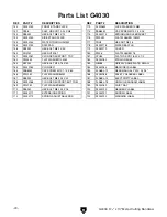
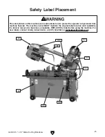
Page 43: ...protect the operator or bystander from machine hazards The machine owner MUST maintain the original label location and readability If a label is removed or becomes unreadable REPLACE the label before...

Page 44: ...y shall be tried in the State of Washington County of Whatcom We shall in no event be liable for death injuries to persons or property or for incidental contingent special or consequential damages ari...

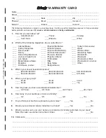
Page 45: ...0 2 Years ____ 2 8 Years ____ 8 20 Years ____20 Years 6 How many of your machines or tools are Grizzly ____ 0 2 ____ 3 5 ____ 6 9 ____10 7 Do you think your machine represents a good value _____Yes __...

Page 46: ...LINE FOLD ALONG DOTTED LINE GRIZZLY INDUSTRIAL INC P O BOX 2069 BELLINGHAM WA 98227 2069 Place Stamp Here Name_______________________________ Street_______________________________ City______________S...

Page 47: ......
Page 48: ...Trusted Proven and a Great Value OR s SECURE ORDERING s ORDERS SHIPPED WITHIN 24 HOURS s E MAIL RESPONSE WITHIN ONE HOUR Visit Our Website Today And Discover Why Grizzly Is The Industry Leader Call To...

Reviews: