-26-
Model G4003 (Mfd. Since 6/20)
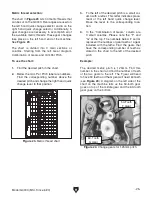
Metric threading requires 5 gear changes to
achieve all of the available pitches listed on
the chart. Refer to
Figure 25 while reading the
instructions below.
To change gears:
1. Loosen the nut below the middle gear and
rotate the bracket so the middle gear moves
away from gear F.
2. Loosen the cap screw at the center of the
middle gear and slide it away from gear G.
3. Gear F can be removed by loosening the cap
screw in its middle. Gear G has a setscrew in
its rim. Loosen this screw and pull the gear
off of the shaft.
4. Replace these two gears with the gears which
will produce the desired pitch and secure with
screws provided.
5. Slide the middle gear until it is in mesh with
the G Gear. Tighten the cap screw at the
center.
6. Pivot the bracket until the middle gear is in
mesh with gear F and tighten the nut below.
Figure 25. Gear placement.
Carriage Controls
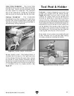
The carriage handwheel allows the cutting tool to
move along the length of the lathe bed. The cross
slide allows the cutting tool to travel perpendicu-
lar to the bed. The carriage features a top slide
which allows linear movement of the cutting tool
at any preset angle. This section will review the
individual controls on the carriage and provide
descriptions of their uses. See
Figure 26.
Compound Slide Handwheel - The Top Slide
Handwheel controls the position of the cutting tool
relative to the workpiece. The top slide is adjust-
able for any angle. The graduated dial is adjust-
able using the same method as the dial on the
cross slide. Angle adjustment is controlled by hex
nuts on the base of the top slide.
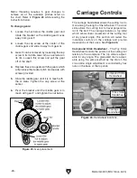
Figure 26. Handwheel locations.
Compound Slide
Handwheel
Cross Slide
Handwheel
Carriage
Handwheel
Summary of Contents for G4003
Page 60: ......

