background image

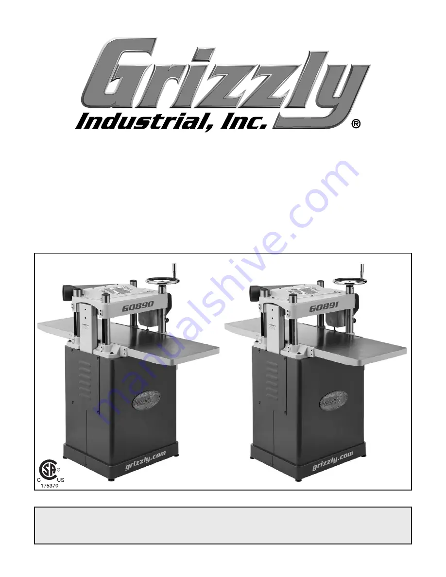
MODEL G0890/G0891

15" FIXED-TABLE PLANERS

OWNER'S MANUAL

(For models manufactured since 06/19)

COPYRIGHT © JULY, 2019 BY GRIZZLY INDUSTRIAL, INC.

WARNING: NO PORTION OF THIS MANUAL MAY BE REPRODUCED IN ANY SHAPE

 OR FORM WITHOUT THE WRITTEN APPROVAL OF GRIZZLY INDUSTRIAL, INC.

#MN20544  PRINTED IN TAIWAN

V1.07.19

Summary of Contents for G0890

Page 1: ...ANUAL For models manufactured since 06 19 COPYRIGHT JULY 2019 BY GRIZZLY INDUSTRIAL INC WARNING NO PORTION OF THIS MANUAL MAY BE REPRODUCED IN ANY SHAPE OR FORM WITHOUT THE WRITTEN APPROVAL OF GRIZZLY...

Page 2: ...g grinding tool integrity and the usage of personal protective equipment The manufacturer will not be held liable for injury or property damage from negligence improper training machine modifications...

Page 3: ...ypes 24 Planing Tips 25 Cutting Problems 25 Depth of Cut 26 Setting Feed Rate 27 Adjusting Replacing Knives G0890 27 Rotating Replacing Cutterhead Inserts G0891 29 SECTION 5 ACCESSORIES 31 SECTION 6 M...

Page 4: ...in this manual Sometimes we make mistakes but our policy of continuous improvement also means that sometimes the machine you receive is slightly different than shown in the manual If you find this to...

Page 5: ...ntrols and features shown below to better understand the instructions in this manual To reduce your risk of serious injury read this entire manual BEFORE using machine Cast Iron Extension Tables Heads...

Page 6: ...workpiece thicknesses One complete revolu tion moves the headstock approximately 5 32 4mm B Feed Rate Control Knob Selects 28 FPM feed rate when pushed in and 16 FPM feed rate when pulled out C Magnet...

Page 7: ...r Figure 2 Workpiece path and major planing components side cutaway view A Anti Kickback Fingers Provide additional safety for the operator B Serrated Infeed Roller Pulls the workpiece toward the cutt...

Page 8: ...Must Ship Upright Yes Electrical Power Requirement 230V Single Phase 60 Hz Full Load Current Rating 12A Minimum Circuit Size 20A Connection Type Cord Plug Power Cord Included Yes Power Cord Length 10...

Page 9: ...Wings Size Width 15 1 2 in Construction Table Precision Ground Cast Iron Body Cast Iron Stand Steel Cutterhead Assembly Steel Infeed Roller Serrated Aluminum Outfeed Roller Rubber Paint Type Finish Po...

Page 10: ...eight 30 x 24 x 49 in Electrical Power Requirement 230V Single Phase 60 Hz Full Load Current Rating 12A Minimum Circuit Size 20A Connection Type Cord Plug Power Cord Included Yes Power Cord Length 10...

Page 11: ...Length 14 in Table Wings Size Width 15 1 2 in Construction Table Precision Ground Cast Iron Body Cast Iron Stand Steel Cutterhead Assembly Steel Infeed Roller Serrated Aluminum Outfeed Roller Rubber P...

Page 12: ...d proof DANGEROUS ENVIRONMENTS Do not use machinery in areas that are wet cluttered or have poor lighting Operating machinery in these areas greatly increases the risk of accidents and injury MENTAL A...

Page 13: ...moving parts or flying debris Make sure they are properly installed undamaged and working correctly BEFORE operating machine FORCING MACHINERY Do not force machine It will do the job safer and better...

Page 14: ...tands for long stock SECURE KNIVES INSERTS Loose knives or improperly set inserts can become dangerous projectiles or cause machine damage Always verify knives inserts are secure and properly adjusted...

Page 15: ...undersized circuit To reduce the risk of these hazards avoid over loading the machine during operation and make sure it is connected to a power supply circuit that meets the specified circuit requirem...

Page 16: ...this machine If you must use an extension cord only use it if absolutely necessary and only on a temporary basis Extension cords cause voltage drop which can damage electrical components and shorten...

Page 17: ...arbox Oil As Needed Unpacking This machine was carefully packaged for safe transport When unpacking separate all enclosed items from packaging materials and inspect them for shipping damage If items a...

Page 18: ...ast Iron Extension Tables 2 C Dust Port 1 D Headstock Elevation Handwheel 1 Tools and Hardware Figure 5 E Hex Bolts M8 1 25 x 25 Ext Tables 6 F Button Head Cap Screws M6 1 x 12 6 G Set Screws M8 1 25...

Page 19: ...posure to toxic fumes Before cleaning gather the following Disposable rags Cleaner degreaser WD 40 works well Safety glasses disposable gloves Plastic paint scraper optional Basic steps for removing r...

Page 20: ...and lon gevity of machine components For best results operate this machine in a dry environment that is free from excessive moisture hazardous chemi cals airborne abrasives or extreme conditions Extr...

Page 21: ...re cov ered or coated in heavy duty rust preventative if applicable 8 Attach dust port to planer with 6 M6 1 x 12 button head cap screws see Figure 12 Figure 12 Dust port installed x 6 3 Using a strai...

Page 22: ...es is beyond the scope of this manual Consult an expert or purchase a good dust collection how to book Checking Gearbox Oil Level Before starting your machine for the first time check the gearbox oil...

Page 23: ...est Run consists of verifying the following 1 The motor powers up and runs correctly and 2 the STOP reset button safety feature functions properly To test run machine 1 Clear all setup tools and loose...

Page 24: ...achine Step by step instructions for these adjustments can be found in the SERVICE section starting on Page 36 Factory adjustments that should be verified Tensioning replacing V belt Page 39 Calibrati...

Page 25: ...ment to reduce your risk from these hazards To complete a typical operation the operator does the following 1 Examines workpiece to make sure it is suit able for planing 2 Puts on safety glasses or fa...

Page 26: ...components Excessive Warping Workpieces with exces sive cupping bowing or twisting are danger ous to cut because they are unstable and often unpredictable when being cut DO NOT use workpieces with th...

Page 27: ...ury or damage to planer Always true cupped or warped stock on a jointer before planing Below is a list of wood characteristics you may encounter when planing The following descrip tions of defects wil...

Page 28: ...educe depth of cut Rippled Cut Problem Regularly spaced indentations across face of workpiece are caused by excessive out feed roller pressure or excessive feed rate Solution Reduce outfeed roller pre...

Page 29: ...nives higher than the cutter head surface refer to distance above Note If you need to replace or sharpen a knife you can remove the knife from the cutter head during Step 4 of the following procedure...

Page 30: ...r pad as shown below 7 Insert hex wrench into access holes in cutterhead see Figure 21 and rotate jack screws to raise or lower knife until it barely touches center pad of knife setting jig with all l...

Page 31: ...head Inserts G0891 The helical cutterhead is equipped with indexable carbide inserts that can be rotated to reveal any one of their four cutting edges If one edge of the insert becomes dull or damaged...

Page 32: ...ny sawdust or debris from head of insert Torx screw and surrounding area see Figure 25 6 Rotate insert 90 and install so that a fresh cutting edge faces outward see Figure 24 When all four insert cutt...

Page 33: ...adjusting infeed outfeed rollers pressure bars chip breakers and bed rollers Also a great setup tool for other machines Accurate to 0 001 Indicator rotates 360 For G0891 H9893 Indexable Carbide Insert...

Page 34: ...n machines of varying heights Adjusts from 265 8 to 45 250 lb capacity G5562 SLIPIT 1 Qt Gel G5563 SLIPIT 12 Oz Spray G2871 Boeshield T 9 12 Oz Spray G2870 Boeshield T 9 4 Oz Spray H3788 G96 Gun Treat...

Page 35: ...s Page 34 Lubricatedrive chain and sprockets Page 35 Yearly Change gearbox oil Page 35 Cleaning Protecting Vacuum excess wood chips and sawdust and wipe off the remaining dust with a dry cloth If any...

Page 36: ...y debris and grime then brush on a light coat of multi purpose grease to the chain and sprockets Figure 35 Example of headstock height chain and sprockets viewed from underneath the base Columns Leads...

Page 37: ...infeed and outfeed rollers Gearbox Oil Oil Type T28042 or ISO 320 Equivalent Oil Amount 20 Oz Frequency After First 20 Hours Then Yearly Note We recommend that you replace the gear box oil after the...

Page 38: ...or replace fuse 5 Correct motor wiring connections 6 Check fix broken disconnected or corroded wires 7 Replace switch 8 Adjust replace centrifugal switch contact points if available 9 Test replace if...

Page 39: ...on slopes down or is not level with main table 2 Workpiece is not supported as it leaves planer 3 Some snipe is inevitable 1 Shim outfeed extension wing level with main table 2 Hold workpiece up sligh...

Page 40: ...29 Uneven cutting marks wavy surface or chatter marks across face of board 1 Feeding workpiece too fast 2 Knives not installed evenly inserts not properly installed 3 Worn cutterhead bearings 1 Slow d...

Page 41: ...after opera tion Allow them to cool before handling Items Needed Qty Hex Wrench 4mm 1 Hex Wrench 6mm 1 To tension replace V belt 1 DISCONNECT MACHINE FROM POWER 2 Remove side panel and belt cover from...

Page 42: ...Knife Insert at BDC Figure 42 A Infeed Roller 0 040 B Outfeed Roller 0 020 feed rollers height It is essential that the feed rollers are set at the correct distance below the cutterhead knives at BDC...

Page 43: ...o neutral position to allow infeed roller to freely rotate 7 Keeping Rotacator dial at 0 position it under right hand side of infeed roller and find BDC of a serrated edge by rocking infeed roller bac...

Page 44: ...move top cover belt cover and gearbox cover 6 Lower headstock until wood blocks get close to cutterhead 7 Use belt to rotate cutterhead and continue lowering headstock until blocks just barely touch c...

Page 45: ...stment screws Tension Screws To adjust feed roller spring tension 1 DISCONNECT MACHINE FROM POWER 2 Rotate tension screws shown below clockwise to increase tension or counter clockwise to decrease ten...

Page 46: ...back Fingers The anti kickback fingers are an important safety feature of your planer The fingers hang from a rod suspended across the head casting and in front of the infeed roller as shown This desi...

Page 47: ...Height Chain Sprockets on Page 34 for detailed instructions then re install motor access panel Figure 51 Headstock height chain adjustment Adjusting Cutterhead Parallelism Maximum Allowable Tolerances...

Page 48: ...e sprockets to keep an accurate tooth count to ensure that the headstock is adjusted equally 5 Mark location of one tooth of sprocket that you are adjusting NOTICE When making adjustments tighten fast...

Page 49: ...t at the time of printing but may not match your machine If you find this to be the case use the wiring diagram inside the motor junction box CAPACITORS INVERTERS Some capacitors and power inverters s...

Page 50: ...it may not match your machine Always use the wiring diagram inside the motor junction box A 96 98 1 2 T1 2 T3 6 NO14 3 4 T2 4 L1 1 L3 5 NO13 L2 3 5 6 95 12 ARC AMP 18 15 NC21 SDE NC22 Ground RESET MAG...

Page 51: ...G0890 G0891 Mfd Since 06 19 49 READ ELECTRICAL SAFETY ON PAGE 47 G0890 G0891 Electrical Components Figure 56 G0890 G0891 motor junction box Figure 55 G0890 G0891 magnetic switch with cover removed...

Page 52: ...41 7 42 43 44 8 91 42 43 44 7 41 33 31 35 40 39 38 37 58 59 32 9 69 74 73 75 69 72 84 69 70 71 69 58 81 76 80 79 77 69 88 82 87 147 193 67 86 65 86 89 83 9 10 66 30 68 85 78 90 C 34 85 C G 113 57 57 1...

Page 53: ...P0890069 BALL BEARING 6201 2NSE 25 P0890025 SET SCREW M6 1 X 16 70 P0890070 SHAFT 26 P0890026 BUTTON HD CAP SCR M6 1 X 25 71 P0890071 GEAR 52T 27 P0890027 FLAT WASHER 6MM 72 P0890072 KEY 5 X 5 X 12 28...

Page 54: ...4 150 154 152 195 152 195 144 154 156 153 A D 155 162 122 120 122 132 156 153 123 135 143 132 154 139 114 125 160 146 127 126 136 121 121 196 139 155 143 196 155 153 115 131 155 154 107 133 108 109 11...

Page 55: ...ASHER 8MM 148 P0890148 HEX WRENCH 4MM 122 P0890122 FLAT WASHER 10MM PLASTIC 149 P0890149 BELT COVER 123 P0890123 GAS STRUT 150 P0890150 MOTOR PLATE 124 P0890124 STAND 151 P0890151 BUTTON HD CAP SCR M6...

Page 56: ...arts Store Table 212 226 227 D 208 221 294 221 294 216 219 221 294 293 296 297 200 298 299 201 202 203 210 298 299 201 202 203 209 246 211 246 205 204 295 E E 208 207 245 214 215 216 217 218 221 222 2...

Page 57: ...224 P0890224 FLAT WASHER 10MM 207 P0890207 KEY 4 X 4 X 20 225 P0890225 DIRECTION LABEL 208 P0890208 SET SCREW M10 1 5 X 12 226 P0890226 HEX BOLT M8 1 25 X 25 209 P0890209 COLUMN 227 P0890227 SET SCRE...

Page 58: ...r o p m a d n i e s u r o n i a r o t e s o p x e t o n o D 3 1 14 Prevent unauthorized use by children or untrained users 175370 302 303 304 305 306 307 308 309 310 311 312 313 Motor 3 HP 230V 1 Ph 6...

Page 59: ...for incidental contingent special or consequential damages arising from the use of our products The manufacturers reserve the right to change specifications at any time because they constantly strive...

Page 60: ......

Reviews: