Grizzly G0886 Owner'S Manual Download Page 49

Model G0886 (Mfd. Since 01/19)

-47-

6.  Clean tank cap and fill screen (see Figure 69

on 

Page 46) with mineral spirits and allow to 

air dry.

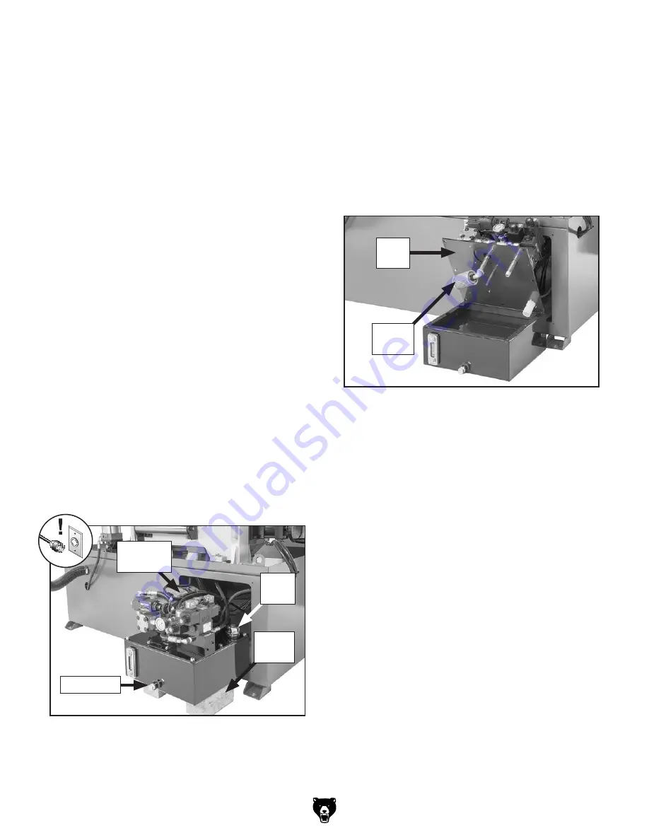
7.  Open  tank  by  removing  (8)  hex  bolts  that 

secure lid (see 

Figure 71).

8.  Clean tank and tank screen (see Figure 71) 

with mineral spirits. Wipe out as much resid-
ual fluid and contaminants from tank as pos-
sible. Allow tank and tank screen to air dry.

9.  Re-install tank lid and screen.

10.  Re-wrap drain plug threads with Teflon tape, 

re-install  drain  plug,  then  fill  tank  with  16 
quarts of ISO 32 or equivalent hydraulic fluid.

11.  Re-install tank cap, slide hydraulic unit back 

into base, and re-install front access panel.

Changing Hydraulic Fluid

To change hydraulic fluid:

1.  Raise/lower headstock repeatedly for approx-

imately 10 minutes to warm up hydraulic fluid.

2.  DISCONNECT MACHINE FROM POWER! 

3.  Remove hydraulic unit access panel on rear  

of machine

.

4.  Slide hydraulic unit out of machine base and 

support  weight  of  hydraulic  unit  with  wood 
blocks (see 

Figure 70).

5.  Remove  tank  cap  (see  Figure  70),  then 

remove  drain  plug  and  allow  tank  to  empty 
into drain pan.

Item(s) Needed 

Qty

T23963 or ISO 32 Equivalent .................... 16 Qt.
Safety Goggles .................................................. 1
Hex Wrench 4mm .............................................. 1 
Wood Blocks ..................................... As Needed
5-Gallon Drain Pan ............................................ 1
Open-End or Socket Wrench 21mm.................. 1
Funnel ................................................................ 1
Clean Shop Rags .............................. As Needed
Mineral Spirits .................................... As Needed
Teflon Thread Tape ........................... As Needed

The  hydraulic  fluid  should  be  changed  and  the 
fluid tank cleaned every 5,000 hours of use.

Figure 70. Hydraulic unit removed from base.

Wood 

Blocks

Tank 

Cap

Hydraulic 

Unit

Drain Plug

Figure 71.

 Hydraulic fluid tank lid removed.

Tank 

Screen

Tank 

Lid

Changing Hydraulic Fluid

Summary of Contents for G0886

Page 1: ...O PORTION OF THIS MANUAL MAY BE REPRODUCED IN ANY SHAPE OR FORM WITHOUT THE WRITTEN APPROVAL OF GRIZZLY INDUSTRIAL INC ES20255 PRINTED IN TAIWAN V1 04 19 MODEL G0886 12 X 14 3 HP AUTO METAL CUTTING BA...

Page 2: ...g grinding tool integrity and the usage of personal protective equipment The manufacturer will not be held liable for injury or property damage from negligence improper training machine modifications...

Page 3: ...Care Break In 31 Changing Blade Speed 32 Blade Speed Chart 33 Chip Inspection Chart 34 Using Vise 35 Blade Guides 35 Setting Headstock Height 36 Setting Blade Feed Rate 36 Feed System 37 Proximity Sen...

Page 4: ...de every effort to be exact with the instruc tions specifications drawings and photographs in this manual Sometimes we make mistakes but our policy of continuous improvement also means that sometimes...

Page 5: ...better understand the instructions in this manual Front View Rear View Control Panel Fixed Vise Jaw Movable Vise Jaw Vise Handwheel Blade Tension Handwheel Blade Guide Scale Proximity Sensor Worklamp...

Page 6: ...headstock must be raised and vise close button K must be pressed F Blade Feed Rate Dial Controls rate at which blade feeds into workpiece G Operation Mode Switch Selects between Auto or Manual operat...

Page 7: ...ps hold workpiece dur ing cutting operations Has rollers that help feed material into cutting position Figure 4 Vise table controls and components U Movable Vise Jaw Holds workpiece during cutting ope...

Page 8: ...ngth x Width 56 x 28 in Shipping Dimensions Type Wood Crate Content Machine Weight 1800 lbs Length x Width x Height 85 x 48 x 62 in Must Ship Upright Yes Electrical Power Requirement 220V 3 Phase 60 H...

Page 9: ...Info Blade Speeds 92 161 236 338 FPM Std Blade Length 155 1 2 in Blade Length Range 155 1 4 155 3 4 in Cutting Capacities Vise Jaw Depth 14 in Vise Jaw Height 6 11 16 in Max Capacity Rectangular Heig...

Page 10: ...d proof DANGEROUS ENVIRONMENTS Do not use machinery in areas that are wet cluttered or have poor lighting Operating machinery in these areas greatly increases the risk of accidents and injury MENTAL A...

Page 11: ...moving parts or flying debris Make sure they are properly installed undamaged and working correctly BEFORE operating machine FORCING MACHINERY Do not force machine It will do the job safer and better...

Page 12: ...ADE CONDITION Do not operate with dull cracked or badly worn blade Inspect blades for cracks and missing teeth before each use HAND PLACEMENT Never position hands or fin gers in line with the cut or u...

Page 13: ...lt especially if connected to an undersized circuit To reduce the risk of these hazards avoid over loading the machine during operation and make sure it is connected to a power supply circuit that mee...

Page 14: ...or service per sonnel if you do not understand these grounding requirements or if you are in doubt about whether the tool is properly grounded If you ever notice that a cord or plug is damaged or worn...

Page 15: ...meets minimum circuit requirements for machine review Power Supply on Page 11 for details An electrician or qualified service person nel to ensure a safe and code compliant connection to power source...

Page 16: ...g The following is a list of items shipped with your machine Before beginning setup lay these items out and inventory them If any non proprietary parts are missing e g a nut or a washer we will gladly...

Page 17: ...Model G0886 Mfd Since 01 19 15 Hardware Recognition Chart USE THIS CHART TO MATCH UP HARDWARE DURING THE INVENTORY AND ASSEMBLY PROCESS 5mm 5mm Flat Head Cap Screw...

Page 18: ...ng gather the following Disposable rags Cleaner degreaser WD 40 works well Safety glasses disposable gloves Plastic paint scraper optional Basic steps for removing rust preventative 1 Put on safety gl...

Page 19: ...low for required space allocation Physical Environment The physical environment where the machine is operated is important for safe operation and lon gevity of machine components For best results oper...

Page 20: ...if safe lifting and moving methods are not fol lowed To be safe you will need assistance and power lifting equipment when moving shipping crate and removing machine from crate Seek assistance from a p...

Page 21: ...feels more solid If the machine will be installed in a commercial or workplace setting or if it is permanently connect ed hardwired to the power supply local codes may require that it be anchored to t...

Page 22: ...14 Proximity sensor bar attached Fixed Vise Jaw Flat Edge 2 Slide proximity sensor bracket assembly onto proximity sensor bar as shown in Figure 15 then tighten adjustable handle Figure 15 Proximity s...

Page 23: ...rate or allow others to operate machine until the information is understood The Test Run verifies the following 1 all motors power up and run correctly 2 the hydraulic system runs correctly 3 3 phase...

Page 24: ...stock button J is pushed then phase polarity is correct Remove related shipping tag from control panel and continue to Step 12 If headstock does not raise or lower when raise headstock button L and lo...

Page 25: ...ed in immediately dis connect power The Emergency Stop but ton safety feature is not working correctly This safety feature must work properly before proceeding with regular operations Call Tech Suppor...

Page 26: ...adjust ments can be found in SECTION 7 SERVICE Factory adjustments that should be verified 1 Blade Tracking Page 54 2 Blade Guides Page 56 3 Squaring Blade to Table Page 58 Disabling Locking Switch Th...

Page 27: ...d refer to Tensioning Blade on Page 30 6 Turns master power switch ON then turns hydraulic pump ON 7 Securely clamps workpiece in vise using manual and hydraulic controls refer to Using Vise on Page 3...

Page 28: ...ved by the blade during cutting B Tooth Set The amount each tooth is bent left or right from the blade C Gauge The thickness of the blade D Blade Width The widest point of the blade measured from the...

Page 29: ...nd shape of material to be cut 4 In applicable row read across to right and find box where row and column intersect Listed in the box is minimum TPI recom mended for variable tooth pitch blades The TP...

Page 30: ...utton to turn hydraulic pump ON 2 Push raise headstock button and raise headstock approximately 6 inches 3 DISCONNECT MACHINE FROM POWER 4 Remove cutoff chute and move proximity sensor out of the way...

Page 31: ...tion Blade Travel 11 Apply a light amount of tension to hold blade in place Work your way around blade to adjust position so back of blade is against shoulder of wheels as shown in Figure 33 12 Perfor...

Page 32: ...f each day to prolong blade life Tensioning Blade Proper blade tension is essential to avoid blade vibration twist or slippage on the wheels A cor rectly tensioned blade provides long blade life strai...

Page 33: ...ppropriate feed rate feed pressure and blade speed and pay attention to the chip characteristics Refer to Blade Speed Chart on Page 33 and Chip Inspection Chart on Page 34 Keep your blades clean since...

Page 34: ...886 has four speed settings 92 161 236 and 338 feet per minute FPM These different speed settings are changed by moving belt position on pulleys see Figure 36 Refer to the chart on Page 33 for cutting...

Page 35: ...Material Speed FPM M Min Material Speed FPM M Min Material Speed FPM M Min Material Speed FPM M Min Carbon Steel 196 354 60 108 Tool Steel 203 62 Alloy Steel 111 321 34 98 Free Machining Stainless Ste...

Page 36: ...g thin straight powdery thin curled tightly hard thin thin curled short hard thick thick hard strong thick hard strong thin straight powdery thin curled tightly hard thin thin curled short hard thick...

Page 37: ...y pressure on movable vise jaw 3 Insert workpiece between jaws Use vise handwheel to move vise jaw until it just con tacts workpiece IMPORTANT Use roller stands or tables to support long workpieces 4...

Page 38: ...ection Chart on Page 34 for more details Setting Headstock Height The height that the headstock will travel is con trolled by the upper limit switch and the height adjustment rod and bracket see Figur...

Page 39: ...ped with motorized rollers that move the workpiece into cutting position The fixed vise jaw has non motorized rollers The roll ers are precisely aligned at the factory and do not require adjustment 1...

Page 40: ...en jaws Use roller stands or tables to support long pieces 3 Turn master power switch ON 4 Push hydraulic pump button to turn hydraulic pump ON 5 Set headstock to required height for workpiece refer t...

Page 41: ...LOGICAL AND POISON HAZARD Use proper per sonal protection equipment when handling coolant and follow federal state and fluid manufacturer require ments to properly dispose of coolant Coolant This band...

Page 42: ...cutting any of these types of containers unless you have verified that the container is empty and it can be properly sup ported during a cut Magnesium Pure magnesium burns eas ily Cutting magnesium w...

Page 43: ...prene seals Great for general purpose or heavy duty applications Can be used on all metals except titanium Figure 51 Typical variable pitch bi metal cutting blade Accessories Basic Eye Protection T205...

Page 44: ...olumn Page 44 Lubricate blade guide arm gib Page 44 Remove blade and clean wheels Check gearbox oil level Page 45 Bi annually Change gearbox oil Page 45 Schedule To reduce risk of shock or accidental...

Page 45: ...rew with 1 2 drops of light machine oil weekly see Figure 60 Wipe off excess oil with a clean rag Figure 60 Blade tension leadscrew Figure 59 Blade and blade guides Lubrication The bearings on your ba...

Page 46: ...hen dry use a clean brush to apply a thin coat of oil to the leadscrew threads see Figure 61 Vise Leadscrew Figure 61 Vise table and vise leadscrew Vise Leadscrew Vise Table Blade Guide Arm Gib Blade...

Page 47: ...eekly The gearbox has a sight tube see Figure 65 to check fluid level The sight tube should be filled with gear oil If it s not remove fill plug with breather tube see Figure 66 and slowly add just en...

Page 48: ...ct a qualified hydraulic service technician or Tech Support 8 Re install tank cap slide hydraulic unit back into base and re install front access panel Always wear safety gog gles when servicing the h...

Page 49: ...ower headstock repeatedly for approx imately 10 minutes to warm up hydraulic fluid 2 DISCONNECT MACHINE FROM POWER 3 Remove hydraulic unit access panel on rear of machine 4 Slide hydraulic unit out of...

Page 50: ...goggles and a NIOSH approved respirator Although most swarf from machining operations is screened out of the coolant before it returns to the tank small particles will accumulate in the bottom of the...

Page 51: ...e Shop Rags As Needed Teflon Thread Tape As Needed 4 Remove coolant pump access panel on left side of machine as shown in Figure 75 5 Thoroughly clean reservoir and pump filter with hot soapy water th...

Page 52: ...siccant Packs As Needed Bringing Machine Out of Storage 1 DISCONNECT MACHINE FROM POWER 2 Remove moisture absorbing desiccant packs from electrical box 3 Re tension blade as described on Page 30 4 Rep...

Page 53: ...Adjust limit switch replace if at fault Page 54 3 Position proximity sensor with 1 4 of workpiece 4 Test all legs for power replace if at fault Headstock does not raise lower 1 Incoming power supply...

Page 54: ...dulls prematurely or metal sticks to blade 1 Blade improperly broken in 2 Blade gullets loading up with chips 3 Blade TPI too fine teeth load up and overheat 4 Incorrect coolant mixture for workpiece...

Page 55: ...3 Vise hydraulic system is leaking 4 Control panel wiring at fault 5 Hydraulic pump at fault 1 Test repair replace 2 Check solenoid plugs 3 Test for leaks repair 4 Check that hydraulic pump motor is...

Page 56: ...lt just begins to press the limit switch trigger 4 While holding stop bolt in place tighten jam nut to secure setting Jam Nut Stop Bolt Limit Switch Adjusting Blade Tracking To adjust blade tracking 1...

Page 57: ...re 80 Blade brush and components Blade Brush Blade Brush Bracket Button Head Cap Screws 4 Adjust blade brush bracket so blade extends approximately 1 8 into bristles of brush then tighten button head...

Page 58: ...ide proceed to Step 6 Adjusting Carbide Blade Guides 6 Loosen cap screws on blade guide arm see Figure 82 and adjust set screw to move blade guide up or down until upper carbide blade guide lightly to...

Page 59: ...o posi tion it is acceptable if there is 0 001 0 002 gap between blade and front or back of bear ing Just make sure not to squeeze blade too tightly with bearings After guide bearings are set you shou...

Page 60: ...ide Arm Cap Screw 1 of 3 Set Screws Squaring Blade to Table This adjustment has been made at the factory and should not need to be adjusted under normal circumstances However if you find the saw is no...

Page 61: ...MOTOR WIRING The motor wiring shown in these diagrams is current at the time of printing but may not match your machine If you find this to be the case use the wiring diagram inside the motor junction...

Page 62: ...Open Contactor UP Headstock Up Contactor DOWN Headstock Down Contactor O Hydraulic Motor Contactor R1 Relay 1A1B R2 Relay 1A R3 DC Relay MODE Operation Mode Switch HAND Feed Roller Switch VOFF Vise O...

Page 63: ...W U1 V1 W1 U3 V3 W3 U2 V2 W2 M1 M3 M2 M4 KM Main Motor Contactor O Hydraulic Motor Magnetic Contactor F Feed Motor Contactor FR1 Main Motor Overload Relay FR2 Hydraulic Motor Overload Relay FR3 Feed M...

Page 64: ...L SAFETY ON PAGE 59 1 26 KM3 24V 0V 27 27 28 28 29 29 KM1 Vise Close Contactor VLV1 Vise Close Valve KM2 Headstock Down Contactor VLV2 Headstock Down Valve KM3 Headstock Up Contactor VLV3 Headstock Up...

Page 65: ...trical Photos Figure 89 Proximity sensor head Figure 88 Control panel components and wiring connections see Page 73 for breakdown of individual components Figure 87 Electrical cabinet components and w...

Page 66: ...wer limit switch wiring connections Figure 94 Coolant pump wiring connections Figure 92 Hydraulic pump motor wiring connections Figure 93 Main motor wiring connections Figure 91 Feed system motor wiri...

Page 67: ...23 25 26 28 29 30 31 32 33 37 38 40 42 43 47 46 85 86 87 90 2 90 1 91 92 93 94 90 90 3 90 4 90 5 95 98 99 101 97 104 8 77 78 80 83 96 102 103 105 106 107 108 79 100 109 110 111 Base SECTION 9 PARTS W...

Page 68: ...TABLE 90 4 P0886090 4 BALL BEARING 6205ZZ FRONT 21 P0886021 LOCK WASHER 12MM 90 5 P0886090 5 BALL BEARING 6203ZZ REAR 22 P0886022 CAP SCREW M12 1 75 X 45 91 P0886091 HYDRAULIC HOSE 1 4 D X 41 1 2 L 23...

Page 69: ...192 191 192 191 192 201 200 202 203 204 205 209 212 210 216 213 214 217 210 212 218 219 220 209 225 224 221 222 223 225 224 221 222 223 220 217 214 218 219 213 216 206 206 230 231 232 233 234 235 232...

Page 70: ...ON GIB 237 P0886237 LOCK WASHER 6MM 159 P0886159 LOCK WASHER 10MM 238 P0886238 CAP SCREW M6 1 X 15 160 P0886160 CAP SCREW M10 1 5 X 25 240 P0886240 IDLER WHEEL COVER 161 P0886161 LOCK WASHER 12MM 241...

Page 71: ...LABEL 275 1 P0886275 1 MOTOR FAN COVER 285 P0886285 PULLEY WASHER 10 X 40 X 6 275 2 P0886275 2 MOTOR FAN 286 P0886286 MOTOR PULLEY BUSHING 275 3 P0886275 3 MOTOR JUNCTION BOX 287 P0886287 PULLEY COVER...

Page 72: ...OIL SEAL 40 X 62 X 9 NBR TC40 308 P0886308 O RING 84 4 X 3 1 G85 333 P0886333 BUSHING 30 X 40 X 16 309 P0886309 GEAR CASE COVER FRONT 334 P0886334 BEARING LOCK NUT M30 1 5 AN06 310 P0886310 O RING 245...

Page 73: ...ur Parts Store Feed System 400 401 402 403 404 405 406 407 408 406 409 424 410 412 411 413 414 2 414 1 414 3 414 4 414 5 414 415 425 416 417 418 419 420 421 422 423 429 437 430 431 432 432 433 434 435...

Page 74: ...EW M8 1 25 X 20 441 P0886441 KNOB M24 2 D50 ROUND KD 414 P0886414 FEED MOTOR 1 8HP 220V 3 PH 442 P0886442 ADJUSTMENT SHAFT BLOCK M10 1 5 414 1 P0886414 1 MOTOR FAN COVER 443 P0886443 COMPRESSION SPRIN...

Page 75: ...5L3 21NC A1 2T1 4T2 6T3 22NC A2 I 0 1L1 3L2 5L3 13NO A1 2T1 4T2 6T3 14NO A2 1L1 3L2 5L3 21 A1 2T1 4T2 6T3 22 A2 1L1 3L2 5L3 21 A1 2T1 4T2 6T3 22 A2 1L1 3L2 5L3 21 A1 A2 22 6T3 4T2 2T1 1L1 3L2 5L3 13NO...

Page 76: ...BUTTON SWITCH NHD CB 10 01 NPB22 F GRN 533 P0886533 FUSE 5A 250V CERAMIC 511 P0886511 BUTTON SWITCH NHD CB 10 NPB22 F GRN 534 P0886534 CONTACTOR NHD C 06D01 24V 512 P0886512 ELECTRONIC COUNTER CONCH C...

Page 77: ...eeves 12 Do not operate when tired or under influence of drugs or alcohol 13 Do not expose to rain or use in wet locations 14 Prevent unauthorized use by children or untrained users restrict access or...

Page 78: ......

Page 79: ...for incidental contingent special or consequential damages arising from the use of our products The manufacturers reserve the right to change specifications at any time because they constantly strive...

Page 80: ......

Reviews: