background image

-4-

Model G0794 (Mfd. Since 05/18)

The laser should be checked and adjusted before 
starting a new project, and any time you raise or 
lower the table, or change workpiece thickness.

Laser Guide

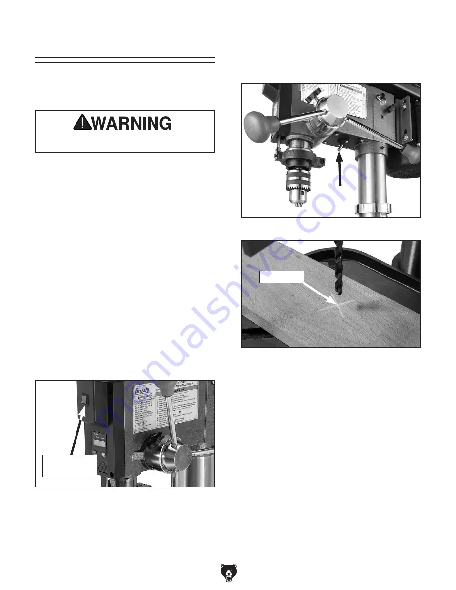
7.  Adjust laser (Figure 2), positioning it by hand 

so crosshairs align with indentation you made 
earlier  in  surface  of  workpiece,  as  shown  in 

Figure 3.

DO NOT look directly into laser. Severe eye 
injury will result.

To adjust laser:

1.  DISCONNECT  DRILL  PRESS  FROM 

POWER!

2.  Install  drill  bit  in  chuck  (see  Installing/

Removing Drill Bits  on  Page 25  of  Model 
G7944 manual).

3.  Clamp workpiece securely to table.

4.   Adjust  table  so  workpiece  is  within  range  of 

drill bit, then lock table in horizontal position.

5.  Lower drill bit so it touches workpiece, mak-

ing  a  slight  indentation  in  the  surface,  then 
raise bit.

6.  Connect  drill  press  to  power.  Turn  laser 

ON  using  switch  on  front  of  drill  press  (see 

Figure 1).

Figure 1. Location of laser ON/OFF switch.

Laser ON/

OFF Switch

Figure 2. Location of laser.

Figure 3. Crosshairs aligned with indentation on 

workpiece.

Indentation

Summary of Contents for G0794

Page 1: ...laser drilling guide in place of the work light Aside from the dif ferences noted in this insert all other content in the Model G7944 owner s manual applies to this machine To reduce the risk of serious injury you MUST read and understand this insert and the entire Model G7944 manual BEFORE assembling installing or operating this machine If you have any further questions about this manual insert o...

Page 2: ... Must Ship Upright No Electrical Power Requirement 110V Single Phase 60 Hz Full Load Current Rating 9A Minimum Circuit Size 15A Connection Type Cord Plug Power Cord Included Yes Power Cord Length 8 1 2 ft Power Cord Gauge 18 AWG Plug Included Yes Included Plug Type 5 15 Switch Type Paddle Safety Switch w Removable Key Motors Main Horsepower 3 4 HP Phase Single Phase Amps 9A Speed 1720 RPM Type TEF...

Page 3: ... Travel Crank Handle Operation Number of T Slots 4 T Slot Size 5 8 in T Slot Centers 3 7 8 in Floor To Table Height 20 46 in Construction Table Precision Ground Cast Iron Column Steel Spindle Housing Cast Iron Head Cast Iron Base Cast Iron Paint Type Finish Enamel Other Related Information Base Length 18 in Base Width 11 in Mobile Base D2260A Column Diameter 3 150 in Depth Stop Type Hub Other Spec...

Page 4: ...ISCONNECT DRILL PRESS FROM POWER 2 Install drill bit in chuck see Installing Removing Drill Bits on Page 25 of Model G7944 manual 3 Clamp workpiece securely to table 4 Adjust table so workpiece is within range of drill bit then lock table in horizontal position 5 Lower drill bit so it touches workpiece mak ing a slight indentation in the surface then raise bit 6 Connect drill press to power Turn l...

Page 5: ...stall DRO unit and DRO housing mak ing sure to re install shoulder screw from Step 2 The model G0794 is equipped with a digital read out DRO for precision spindle adjustment The DRO is independently powered by a SR44 but ton cell battery which may need to be changed from time to time Follow the instructions below to change the battery Tools Needed Qty Phillips Head Screwdriver 2 1 To change DRO ba...

Page 6: ...iagrams is current at the time of printing but may not match your machine If you find this to be the case use the wiring diagram inside the motor junction box CAPACITORS INVERTERS Some capacitors and power inverters store an electrical charge for up to 10 minutes after being disconnected from the power source To reduce the risk of being shocked wait at least this long before working on capacitors ...

Page 7: ...Motor Junction Box LR44 Battery Neutral Hot Ground 110 VAC 5 15 Plug Laser ON OFF Switch KDC01 101 2 8A 250VDC 1 1A S Capacitor 125VAC 200uF IN 120VAC OUT 3VDC TRANSFORMER GAO YOU Start Capacitor Figure 7 Start capacitor G0794 Wiring Laser Figure 6 Laser and transformer Transformer Figure 8 Motor junction box and terminal block Ground To Motor From Plug ...

Page 8: ... 41 42 43 44 45 46 48 49 50 51 52 53 54 55 56 56 28 57 58 58 1 58 2 58 3 58 4 58 6 58 7 58 8 58 9 58 10 59 60 61 62 63 64 65 66 67 68 144 69 70 71 72 73 74 75 76 77 78 79 80 81 82 83 84 85 86 87 88 89 90 91 92 97 98 99 100 104 105 101 119 102 103 110 113 115 116 120 121 122 123 124 125 126 127 128 129 130 131 132 133 134 135 136 136 137 137 138 58 11V2 ...

Page 9: ...CR M6 1 X 10 26 P0794026 DOWNFEED HANDLE M12 1 75 MALE 70 P0794070 PHLP HD SCR M5 8 X 10 27 P0794027 DOWNFEED KNOB M12 1 75 FEMALE 71 P0794071 FLAT WASHER 5MM 28 P0794028 LOCK WASHER 12MM 72 P0794072 PULLEY COVER KNOB M5 8 29 P0794029 KNOB BOLT M8 1 25 X 22 73 P0794073 PULLEY COVER 30 P0794030 SET SCREW M10 1 5 X 12 74 P0794074 V BELT M25 32 P0794032 EXT RETAINING RING 16MM 75 P0794075 PULLEY NUT ...

Page 10: ...ECTING PLATE 113 P0794113 ANGLE SCALE 131 P0794131 HEX NUT M3 5 115 P0794115 CAP SCREW M8 1 25 X 20 132 P0794132 PHLP HD SCR M3 5 X 10 116 P0794116 STRAIN RELIEF 1 4 5 16 ST PLASTIC 133 P0794133 LASER LIGHT RETAINING PLATE 118 P0794118 ANGLE INDICATOR 134 P0794134 PHLP HD SCR M5 8 X 8 119 P0794119 MOTOR LABEL 135 P0794135 LASER TRANSFORMER BRACKET 120 P0794120 CRANK LEVER 136 P0794136 PHLP HD SCR ...

Page 11: ...MUST replace it in the original location before resuming operations For replacements contact 800 523 4777 or www grizzly com Labels Cosmetics REF PART DESCRIPTION REF PART DESCRIPTION 139 P0794139 ELECTRICITY LABEL 142 P0794142 MACHINE ID LABEL 140 P0794140 READ ENTANGLE GLASSES LABEL 143 P0794143 MODEL NUMBER LABEL 141 P0794141 POWER PINCH HAZARD LABEL 139 143 139 140 141 139 142 ...

Page 12: ... 12 Model G0794 Mfd Since 05 18 ...

Reviews: