background image

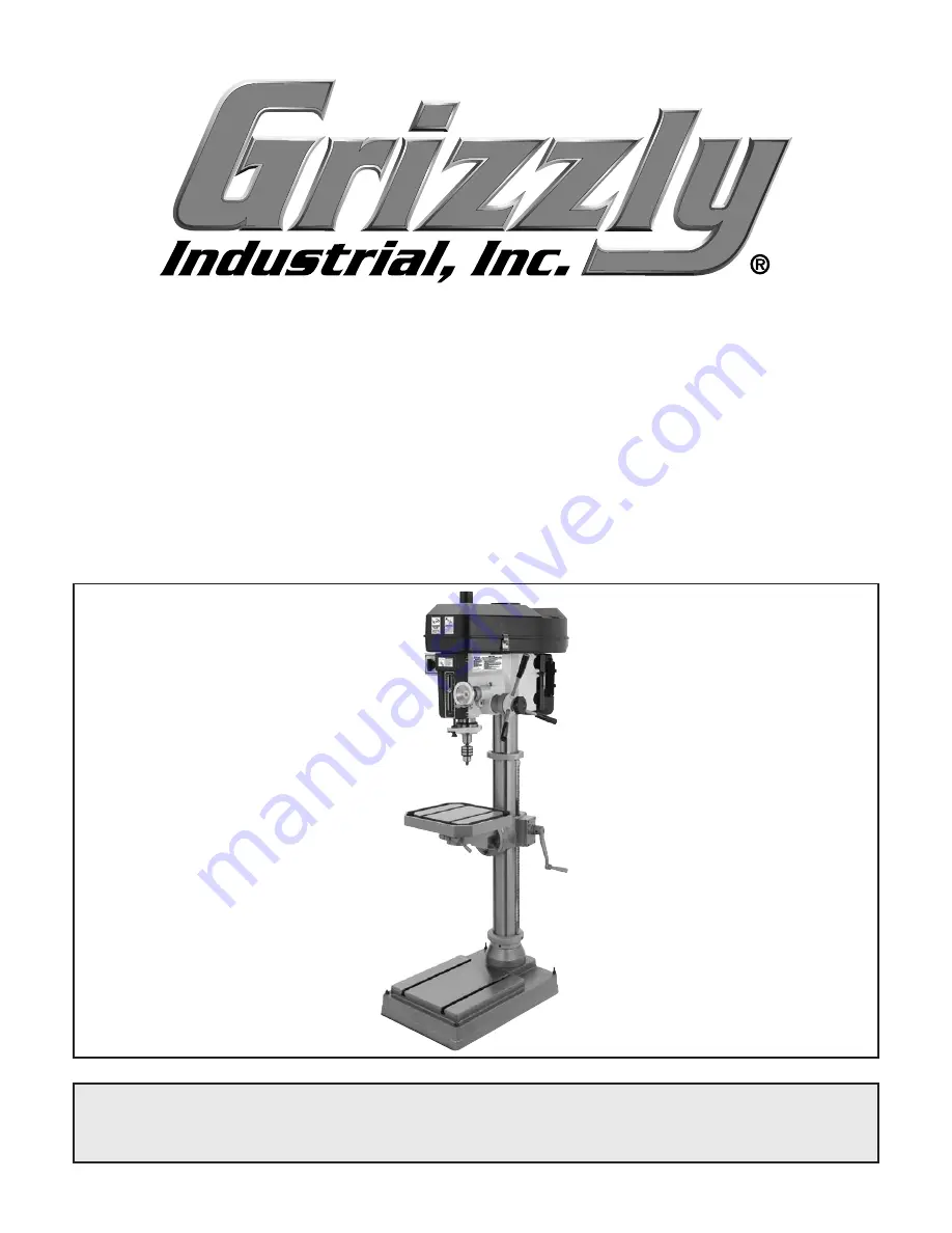
MODEL G0784

15" HEAVY-DUTY

FLOOR DRILL PRESS

OWNER'S MANUAL

(For models manufactured since 03/15)

COPYRIGHT © APRIL, 2015 BY GRIZZLY INDUSTRIAL, INC.

WARNING: NO PORTION OF THIS MANUAL MAY BE REPRODUCED IN ANY SHAPE

 OR FORM WITHOUT THE WRITTEN APPROVAL OF GRIZZLY INDUSTRIAL, INC.

#WKBLMN17372  PRINTED IN CHINA

V1.04.15

Summary of Contents for G0784

Page 1: ...ANUAL For models manufactured since 03 15 COPYRIGHT APRIL 2015 BY GRIZZLY INDUSTRIAL INC WARNING NO PORTION OF THIS MANUAL MAY BE REPRODUCED IN ANY SHAPE OR FORM WITHOUT THE WRITTEN APPROVAL OF GRIZZLY INDUSTRIAL INC WKBLMN17372 PRINTED IN CHINA V1 04 15 ...

Page 2: ...ng grinding tool integrity and the usage of personal protective equipment The manufacturer will not be held liable for injury or property damage from negligence improper training machine modifications or misuse Some dust created by power sanding sawing grinding drilling and other construction activities contains chemicals known to the State of California to cause cancer birth defects or other repr...

Page 3: ...ct Info 2 Manual Accuracy 2 Identification 3 Controls Components 4 Machine Data Sheet 5 SECTION 1 SAFETY 7 Safety Instructions for Machinery 7 Additional Safety for Drill Presses 9 SECTION 2 POWER SUPPLY 10 SECTION 3 SETUP 12 Unpacking 12 Needed for Setup 12 Inventory 12 Cleanup 13 Site Considerations 14 Lifting Placing 15 Anchoring to Floor 15 Joining Drill Chuck Arbor 16 Power Connection 16 Test...

Page 4: ...p Before calling make sure you write down the Manufacture Date and Serial Number from the machine ID label see below This information is required for us to provide proper tech support and it helps us determine if updated documenta tion is available for your machine Manufacture Date Serial Number Manual Accuracy We stand behind our machines If you have ques tions or need help contact us with the in...

Page 5: ...ilt Clamp B Table Lock Handles C Quill Lock Handle D Headstock Elevation Crank E Belt Cover F Fine Downfeed Handwheel G Table H Pivot Lock Handle I Chuck J Spindle K Depth Stop Adjustment Knob L Depth Stop Scale M Spindle Direction Switch N Drawbar Cap O Motor P Motor Locking Lever Q Coarse Downfeed Lever R Column S Rack T Table Elevation Crank U Base B D E F Q C H G I J K L M N O R S T U A P ...

Page 6: ...n to maintain belt ten sion Figure 2 Headstock controls left J H I H Headstock Elevation Crank Changes ele vation of entire headstock along column I Fine Downfeed Handwheel When rotated provides fine vertical control in either direc tion of spindle travel J Quill Lock Locks quill in position Table K Table Lock Handles Secure table assem bly in place along column Loosen to raise or lower table or t...

Page 7: ...x 73 in Must Ship Upright Yes Electrical Power Requirement 220V Single Phase 60 Hz Full Load Current Rating 8 6A Minimum Circuit Size 15A Connection Type Cord Plug Power Cord Included Yes Power Cord Length 6 1 2 ft Power Cord Gauge 14 AWG Plug Included No Recommended Plug Type 6 15 Switch Type Forward Reverse Switch Motors Main Type TEFC Capicitor Start Induction Horsepower 2 HP Phase Single Phase...

Page 8: ...able Length 15 in Table Width 14 in Table Thickness 1 5 8 in Vertical Table Travel Crank Handle Operation Number of T Slots 2 T Slot Size 1 2 in T Slot Centers 10 13 16 in Floor To Table Height 18 1 2 41 3 4 in Construction Table Cast Iron Column Cast Iron Spindle Housing Cast Iron Head Cast Iron Base Cast Iron Paint Type Finish Enamel Other Related Information Base Length 25 1 2 in Base Width 17 ...

Page 9: ...proof DANGEROUS ENVIRONMENTS Do not use machinery in areas that are wet cluttered or have poor lighting Operating machinery in these areas greatly increases the risk of accidents and injury MENTAL ALERTNESS REQUIRED Full mental alertness is required for safe operation of machin ery Never operate under the influence of drugs or alcohol when tired or when distracted For Your Own Safety Read Instruct...

Page 10: ... moving parts or flying debris Make sure they are properly installed undamaged and working correctly BEFORE operating machine FORCING MACHINERY Do not force machine It will do the job safer and better at the rate for which it was designed NEVER STAND ON MACHINE Serious injury may occur if machine is tipped or if the cutting tool is unintentionally contacted STABLE MACHINE Unexpected movement dur i...

Page 11: ...old a workpiece by hand while drilling DO NOT wear gloves when operating the drill SECURING BIT Properly tighten and securely lock the drill bit in the chuck CORRECT BIT Use only round hex or triangular shank drill bits ADJUSTING KEYS AND WRENCHES Remove all adjusting keys and wrenches before turning the machine ON DRILLING SHEET METAL Never drill sheet metal unless it is securely clamped to the t...

Page 12: ...ting or fire may result especially if connected to an undersized circuit To reduce the risk of these hazards avoid over loading the machine during operation and make sure it is connected to a power supply circuit that meets the specified circuit requirements For your own safety and protection of property consult an electrician if you are unsure about wiring practices or electrical codes in your ar...

Page 13: ...ice per sonnel if you do not understand these grounding requirements or if you are in doubt about whether the tool is properly grounded If you ever notice that a cord or plug is damaged or worn discon nect it from power and immediately replace it with a new one Serious injury could occur if you connect machine to power before completing setup process DO NOT connect to power until instructed later ...

Page 14: ...es 1 Cleaner Degreaser Page 13 As Needed Disposable Shop Rags As Needed Forklift 1 Lifting Sling Rated 1000 lbs Minimum 2 Needed for Setup Inventory The following is a list of items shipped with your machine Before beginning setup lay these items out and inventory them If any non proprietary parts are missing e g a nut or a washer we will gladly replace them or for the sake of expediency replaceme...

Page 15: ...ic paint scraper optional Basic steps for removing rust preventative 1 Put on safety glasses 2 Coat the rust preventative with a liberal amount of cleaner degreaser then let it soak for 5 10 minutes 3 Wipe off the surfaces If your cleaner degreas er is effective the rust preventative will wipe off easily If you have a plastic paint scraper scrape off as much as you can first then wipe off the rest...

Page 16: ...rated is important for safe operation and lon gevity of machine components For best results operate this machine in a dry environment that is free from excessive moisture hazardous chemi cals airborne abrasives or extreme conditions Extreme conditions for this type of machinery are generally those where the ambient temperature range exceeds 41 104 F the relative humidity range exceeds 20 95 non co...

Page 17: ...ing to Floor Anchoring machinery to the floor prevents tipping or shifting and reduces vibration that may occur during operation resulting in a machine that runs slightly quieter and feels more solid If the machine will be installed in a commercial or workplace setting or if it is permanently connect ed hardwired to the power supply local codes may require that it be anchored to the floor If not r...

Page 18: ...ey separate repeat Steps 3 4 Power Connection Electrocution or fire may occur if machine is ungrounded incorrectly connected to power or connected to an under sized circuit Use an electri cian or a qualified service personnel to ensure a safe power connection Before the machine can be connected to the power supply there must be an electrical cir cuit that meets the Circuit Requirements on Page 10 ...

Page 19: ...sition to turn spindle ON The motor should run smoothly and without unusual problems or noises 4 Rotate spindle switch to STOP position to turn spindle OFF Allow spindle to come to a complete stop 5 Turn spindle switch to LEFT position to turn spindle ON The motor should run smoothly and without unusual problems or noises 6 Rotate spindle switch to STOP position to turn spindle OFF Allow spindle t...

Page 20: ...PM b 413 RPM c 819 RPM d 1450 RPM e 2436 RPM 5 Turn machine OFF Congratulations Spindle break in is now complete The spindle break in procedure distributes lubri cation throughout the bearings to reduce the risk of early bearing failure if there are any dry spots or areas where lubrication has settled in the bear ings You must complete this procedure before placing operational loads on the spindle...

Page 21: ... later in this manual are easier to understand Due to the generic nature of this overview it is not intended to be an instructional guide To learn more about specific operations read this entire manual seek additional training from experienced machine operators and do additional research outside of this manual by reading how to books trade magazines or websites 1 Examines workpiece to make sure it...

Page 22: ...ass Aluminum Mild Steel 3 8 1 2 1200 1000 5 8 1 800 600 Using the Drill Bit Speed Chart The chart shown in Figure 11 is intended as a guide only Always follow the manufacturer s speed recommendations if provided with your drill bits cutters or hole saws Exceeding the recommended speeds may be dangerous to the operator The speeds shown here are intended to get you started The optimum speed will alw...

Page 23: ...dle Pulley Idler Pulley Motor Pulley 2 3 4 5 6 8 1 7 RPM Position RPM Position 140 4 5 819 1 6 219 3 5 1075 2 7 263 4 6 1238 3 8 317 2 5 1450 1 7 413 3 6 1770 2 8 475 4 7 2436 1 8 Figure 14 Spindle speed chart Changing Spindle Speed The Model G0784 is capable of twelve different spindle speed RPMs Spindle speed is controlled by the configuration of V belts and pulleys located inside the belt cover...

Page 24: ... and down on the lever nearest you The spindle will go down as far as it can until you stop pulling or until it hits the depth stop then it will automatically return to the top when you release pressure on the handle Note Do not let go of the handle until the spindle returns to the top position or the spindle will slam upward into the quill Use the fine downfeed handwheel to control the spindle tr...

Page 25: ...or collet into spindle hous ing then rotate arbor collet to align keyway with matching pin in spindle opening 5 Using lug wrench included with machine rotate top of drawbar clockwise see Figure 17 until drawbar threads mesh with female threads arbor collet Tip If necessary insert included drill chuck key into chuck to hold chuck in place when loosening drawbar Installing Tooling 1 DISCONNECT MACHI...

Page 26: ... intended for high tolerance precision results To calibrate the depth stop see Calibrating Depth Stop on Page 32 Figure 21 Depth stop controls Knurled Knob Indicator The headstock height and rotation can be adjust ed as needed for various applications For the best results fully retract the quill and set the headstock as low as possible to increase quill rigidity and reduce vibration To adjust head...

Page 27: ...rols 3 Tilt table until pointer aligns with desired angle on scale see Figure 23 4 Retighten tilt lock nuts Tilt Lock Nuts Tilt Angle Pointer and Scale 1 Remove any loose objects from table surface 2 Loosen rotation lock handle shown in Figure 22 Rotating Table on its Axis 1 Remove any loose objects from table surface 2 Loosen table lock handles shown in Figure 22 3 Adjust table height by rotating...

Page 28: ... Reflective S Glasses H0736 Shop Fox Safety Glasses H7194 Bifocal Safety Glasses 1 5 H7195 Bifocal Safety Glasses 2 0 H7196 Bifocal Safety Glasses 2 5 Figure 25 Clamping Kit Figure 26 Safety glasses Figure 24 6 Cast iron drill press vise Installing unapproved accessories may cause machine to malfunction resulting in serious personal injury or machine damage To reduce this risk only install accesso...

Page 29: ... R 8 Quick Change Collet 8 Pc Set These collets are hardened and ground for maxi mum holding power and ultra precision Threaded fro 7 16 20 draw bars this set has a maximum run out of 0 001 Set includes collect chuck 1 4 5 16 3 8 1 2 5 8 3 4 and 1 collets spanner wrench and moulded plastic case Figure 28 T26688 R 8 Quick Change Collet 8 pc Set order online at www grizzly com or call 1 800 523 4777...

Page 30: ...st wood chips and metal chips left on the machine will invite oxidation and a gummy residue buildup around the moving parts Use a brush and shop vacuum to remove chips and debris from the working surfaces of the mill Never blow off the mill with compressed air as this will force metal chips deep into the mechanisms and may cause injury to yourself or bystanders Remove any rust build up from unpain...

Page 31: ...ation of light machine oil is all that is neces sary For the quill and column racks lubricate with NLGI 2 grease every 90 days Before applying lubricant clean off any dust or metal chips Your goal is to achieve adequate lubrication Too much lubrication will attract dirt and dust which could cause various parts of your machine to lose their freedom of movement NOTICE Follow reasonable lubrication p...

Page 32: ...ast 3 Belt s slipping 4 Machine undersized for task 5 Plug receptacle at fault 6 Motor overheated 7 Run capacitor at fault 8 Pulley slipping on shaft 9 Centrifugal switch at fault 10 Motor bearings at fault 1 Use correct cutter bit 2 Decrease feed rate cutting speed 3 Ensure belts are oil free tension replace belt s ensure pulleys are aligned 4 Perform operation with different machine 5 Test for g...

Page 33: ... lock lever Page 22 Headstock is hard to raise 1 Headstock lock nuts at fault 2 Rack and pinion at fault or jammed with grime debris 1 Loosen replace lock nuts 2 Fix replace broken or loose parts clean and lubricate rack and pinion Bad surface finish 1 Spindle speed too fast for workpiece material 2 Dull or incorrect cutting tool 3 Wrong rotation direction of cutting tool 4 Workpiece not secure 5 ...

Page 34: ...he spring cap and rapidly unwind laceration or impact inju ries could occur Always wear heavy leather gloves and safety glasses when adjusting the return spring tension Figure 34 Spring tension components Thumb Knob Spring Cover Roll Pin 4 Wearing gloves pull spring cover Figure 35 out enough so notches just clear roll pin HOLD SPRING COVER TIGHTLY during this step or force of spring will cause co...

Page 35: ...diagrams is current at the time of printing but may not match your machine If you find this to be the case use the wiring diagram inside the motor junction box CAPACITORS INVERTERS Some capacitors and power inverters store an electrical charge for up to 10 minutes after being disconnected from the power source To reduce the risk of being shocked wait at least this long before working on capacitors...

Page 36: ...ICAL SAFETY ON PAGE 33 Electrical Components Figure 37 Electrical component wiring overview Figure 40 Motor junction box wiring Motor Spindle Switch Motor Junction Box Figure 38 Switch box wiring right side Figure 39 Switch box wiring left side ...

Page 37: ... 4 6 8 12 10 Spindle Switch Left Side Right Side L L V2 V1 U2 220V Motor N Ground PE V2 V2 V1 U2 V2 U2 U2 V1 U1 Z1 Z2 Z1 W1 U1 Start Capacitor 150 MFD 250 VAC PE Ground U1 V2 U2 V1 N L L U1 V2 V1 U2 6 15 Plug As Recommended Hot Hot Ground 220 VAC G Run Capacitor 20 MFD 450 VAC PE Wiring Diagram ...

Page 38: ... 93 98 99 97 77 77 95 98 2 98 1 98 3 98 4 98 8 98 7 98 5 98 6 98 9 1 2 6 10 58 59 60 61 62 12 13 14 15 16 17 18 19 22 23 20 21 24 27 25 26 28 29 31 30 32 33 33 34 34 37 36 35 38 39 40 41 42 43 44 45 46 47 48 49 49 50 51 52 53 54 55 56 57 67 68 69 71 72 73 63 64 64 65 66 101 116 102 103 104 105 106 106 107 109 76 70 111 110 108 112 113 114 115 ...

Page 39: ...BELT TENSION CAP RUBBER 24 P0784024 INT THREADED BOLT M16 2 X 20 74 P0784074 BELT COVER 25 P0784025 KNURLED THUMB SCREW M12 1 75 X 230 75 P0784075 BELT COVER GUARD 26 P0784026 ROLL PIN 3 X 18 76 P0784076 DRAWBAR COVER 27 P0784027 HEX NUT M16 2 THIN 77 P0784077 FLAT WASHER 8MM 28 P0784028 DEPTH GAUGE LEADSCREW 78 P0784078 HEX BOLT M8 1 25 X 20 29 P0784029 DEPTH ROD DOG 79 P0784079 PULLEY IDLER PLAT...

Page 40: ... CRANK BRACKET 110 P0784110 SHOULDER SCREW M10 1 5 X 10 11 X 45 102 P0784102 WORM SHAFT BUSHING 111 P0784111 CAP SCREW M6 1 X 20 103 P0784103 ELEVATION WORM SHAFT 112 P0784112 SWITCH BOX 104 P0784104 ELEVATION GEAR SHAFT 113 P0784113 SWITCH BOX COVER 105 P0784105 HELICAL GEAR 15T 114 P0784114 ROTARY SWITCH CANSEN LW5D 16 106 P0784106 EXT RETAINING RING 14MM 115 P0784115 CAP SCREW M4 7 X 6 107 P078...

Page 41: ...Model G0784 Mfd since 03 15 39 201 202 203 204 205 207 208 213 209 210 211 206 212 216 215 214 217 218 219 220 221 222 221 224 225 226 240 247 241 242 243 245 244 243 248 246 249 250 Base Breakdown ...

Page 42: ...HAFT 210 P0784210 TABLE RACK 242 P0784242 SPACER 211 P0784211 FIXED GUIDE RING 243 P0784243 EXT RETAINING RING 14MM 212 P0784212 SET SCREW M10 1 5 X 8 244 P0784244 HELICAL GEAR 15T 213 P0784213 CAP SCREW M10 1 5 X 40 245 P0784245 WORM GEAR SHAFT 214 P0784214 FLAT WASHER 16MM 246 P0784246 TABLE ELEVATION CRANK 215 P0784215 LOCK WASHER 16MM 247 P0784247 SET SCREW M10 1 5 X 12 216 P0784216 CAP SCREW ...

Page 43: ...10 P0784310 HEX NUT M14 2 303 P0784303 LUG WRENCH 20 25MM 311 P0784311 DRIFT KEY 304 P0784304 WRENCH 17 X 19MM OPEN ENDS 312 P0784312 SPINDLE SLEEVE MT 3 X MT 2 305 P0784305 HEX WRENCH 5MM 313 P0784313 SPINDLE SLEEVE R 8 X MT 3 306 P0784306 HEX WRENCH 4MM 314 P0784314 DRILL CHUCK ARBOR R8 X B16 307 P0784307 HEX WRENCH 3MM 315 P0784315 DRILL CHUCK B16 1 13MM 308 P0784308 T BOLT M14 2 X 55 316 P0784...

Page 44: ...e to table to prevent rotation 9 Avoid positioning hands where they could slip into rotating bits 10 Always remove chuck keys and other tools before starting 11 Never attempt to slow or stop spindle with hands or tools 12 Use correct speeds for drilling accessories and workpiece 13 Do not operate when tired or under influence of drugs or alcohol 14 Do not expose to rain or use in wet locations 15 ...

Page 45: ... metalworker ____ 0 2 Years ____ 2 8 Years ____ 8 20 Years ____20 Years 6 How many of your machines or tools are Grizzly ____ 0 2 ____ 3 5 ____ 6 9 ____10 7 Do you think your machine represents a good value _____Yes _____No 8 Would you recommend Grizzly Industrial to a friend _____Yes _____No 9 Would you allow us to use your name as a reference for Grizzly customers in your area Note We never use ...

Page 46: ...D LINE FOLD ALONG DOTTED LINE GRIZZLY INDUSTRIAL INC P O BOX 2069 BELLINGHAM WA 98227 2069 Place Stamp Here Name_______________________________ Street_______________________________ City______________State______Zip______ Send a Grizzly Catalog to a friend ...

Page 47: ... shall be tried in the State of Washington County of Whatcom We shall in no event be liable for death injuries to persons or property or for incidental contingent special or consequential damages arising from the use of our products To take advantage of this warranty contact us by mail or phone and give us all the details We will then issue you a Return Number which must be clearly posted on the o...

Page 48: ......

Reviews: