


Model G0756 (Mfg. Since 2/13)
-55-
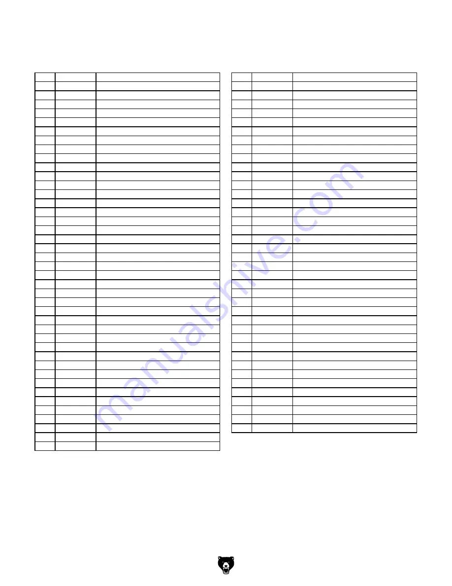
REF PART #
DESCRIPTION
REF PART #
DESCRIPTION
301
P0756301
HEADSTOCK HOUSING
343
P0756343
SPINDLE
302
P0756302
AUTO DOWNFEED SHIFTING FORK
344
P0756344
QUILL
303
P0756303
DOWEL PIN 10 X 20MM
345
PR97M
EXT RETAINING RING 75MM
304
P0756304
AUTO DOWNFEED SHIFTING SHAFT
346
P0756346
O-RING 85 X 5.7
305
P0756305
AUTO DOWNFEED INDICATOR HUB
347
P0756347
THRUST WASHER
306
PSS128M
SET SCREW M8-1.25 X 25 PILOT
348
P51108
THRUST BEARING 51108
307
P0756307
AUTOMATIC DOWNFEED DIAL
349
P0756349
NEEDLE ROLLER BEARING RNA49/32
308
PSTB003M
STEEL BALL 6MM
350
P0756350
SPRING HOUSING
309
P0756309
COMPRESSION SPRING 0.8 X 5 X 16
351
P6006-2RS
BALL BEARING 6006-2RS
310
PSS06M
SET SCREW M8-1.25 X 16
352
P0756352
CLAMP NUT
311
PSTB003M
STEEL BALL 6MM
353
PCAP41M
CAP SCREW M4-.7 X 14
312
P0756312
COMPRESSION SPRING 0.8 X 7 X 12
354
P0756354
DOWEL PIN 12 X 50MM
313
P0756313
AUTOMATIC DRIFT SHAFT
355
P0756355
COMPRESSION SPRING
314
PSS128M
SET SCREW M8-1.25 X 25 PILOT
356
P0756356
GEAR 32/20T
315
PN46M
HEX NUT M8-1.25 THIN
357
PR11M
EXT RETAINING RING 25MM
316
PS14M
PHLP HD SCR M6-1 X 12
358
P0756358
BEARING FLAT WASHER
317
P0756317
COILED SPRING COVER PLATE
359
P6205-2RS
BALL BEARING 6205-2RS
318
PCAP02M
CAP SCREW M6-1 X 20
360
PR26M
INT RETAINING RING 52MM
319
P0756319
CURVED PLATE
361
PR26M
INT RETAINING RING 52MM
320
PRIV003M
STEEL FLUTED RIVET 2 X 4MM
362
P6205-2RS
BALL BEARING 6205-2RS
321
P0756321
INDEX RING
363
P0756363
WOODRUFF KEY 6 X 18
322
PS14M
PHLP HD SCR M6-1 X 12
364
P0756364
SHAFT
323
P0756323
PLATE
365
P0756365
WOODRUFF KEY 6 X 12
324
PCAP95M
CAP SCREW M5-.8 X 30
366
P0756366
GEAR 22T
325
P0756325
FIREWALL PLATE
367
PR11M
EXT RETAINING RING 25MM
326
P0756326
SLIDE PLATE
368
PR12M
EXT RETAINING RING 35MM
327
P0756327
PIN
369
PR29M
INT RETAINING RING 32MM
328
P0756328
BRACKET
370
P6002-2RS
BALL BEARING 6002-2RS
329
P0756329
DRAIN PLUG 3/8" NPT SOCKET HEAD
371
PR29M
INT RETAINING RING 32MM
330
PS14M
PHLP HD SCR M6-1 X 12
372
P0756372
WORM
331
P0756331
CHIP GUARD ASSEMBLY
373
P0756373
NEEDLE ROLLER BEARING MF-2516
332
P0756332
CONTROL PANEL COVER PLATE
374
P0756374
KEYED SPACER
333
P0756333
STAR KNOB 5-PT M10-1.5 X 40
375
P0756375
GEAR 48/60T
334
PCAP03M
CAP SCREW M5-.8 X 8
376
P0756376
KEYED SPACER
335
PSS120M
SET SCREW M6-1 X 16 CONE
377
P0756377
DOWEL PIN 6 X 8MM
336
P0756336
FLANGED COLLAR
378
P0756378
DISC SPRING 45 X 24 X 1.75
337
PCAP12M
CAP SCREW M8-1.25 X 40
379
P0756379
CLAMP NUT
338
PRP16M
ROLL PIN 3 X 25
380
P0756380
PLUNGER
339
P0756339
QUILL COLLAR
381
PSS20M
SET SCREW M8-1.25 X 8
340
P0756340
QUILL COLLAR SHAFT
382
P0756382
ROUND COVER PLATE W/ LUBE HOLE
341
P0756341
TORQUE LIMITER COVER PLATE
342
PS14M
PHLP HD SCR M6-1 X 12
headstock Parts List
Summary of Contents for G0756
Page 64: ......


