Grizzly G0728 Owner'S Manual Download Page 32

-30-

Models G0728–31 (Mfg. Since 11/11)

SECTION 5: ACCESSORIES

aCCEssoriEs

G1075—52-pC. Clamping Kit
this clamping kit includes 24 studs, 6 step block 
pairs, 6 t-nuts, 6 flange nuts, 4 coupling nuts, and 
6 end hold-downs. the rack is slotted so it can be 
mounted  close  to  the  machine  for  easy  access. 
Made for 

1

2

" t-slots.

figure 39. g1075 52-pC. Clamping Kit.

T10063—Milling Vise 12

5

16

" x 6

9

16

"

T10064—Milling Vise 17

1

8

" x 8

3

4

"

• 

ultra precise in flatness, parallelism and ver-
ticality.

• 

anti-lift  mechanism  ensures  the  workpiece 
does not lift when jaws are tightened.

• 

Ductile iron body.

• 

Flame hardened vise bed and jaws.

• 

sealed bearing system.

• 

8200 lbs. of clamping pressure.

figure 38. t10064 Milling vise (handle included, 

but not shown.

Some aftermarket accessories  can be 

installed on this machine that  could  cause 

it to function improperly, increasing the risk 

of serious personal injury. To minimize this 

risk, only install accessories recommended 

for this machine by Grizzly.

NOTICE

Refer to the newest copy of the Grizzly 

Catalog for other accessories available for 

this machine. 

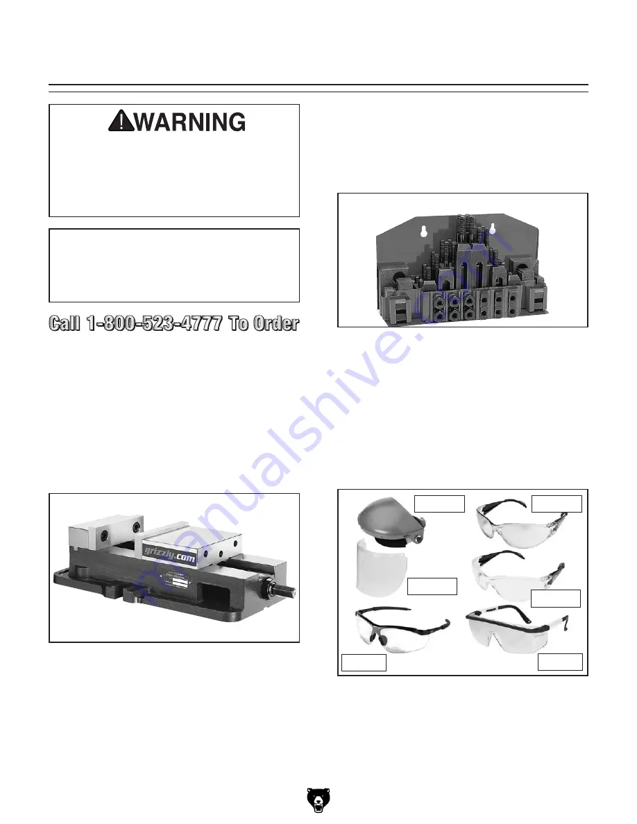
T20501—face Shield Crown protector 4"
T20502—face Shield Crown protector 7"
T20503—face Shield Window
T20452—"Kirova" Anti-Reflective S. Glasses
T20451—"Kirova" Clear Safety Glasses
H0736—Shop fox

®

 Safety Glasses

H7194—bifocal Safety Glasses 1.5
H7195—bifocal Safety Glasses 2.0
H7196—bifocal Safety Glasses 2.5

figure 40. Eye protection assortment.

T20451

H0736

T20452

T20502

T20503

H7194

Summary of Contents for G0728

Page 1: ...ual For models manufactured since 11 11 Copyright DECEMBER 2011 By Grizzly Industrial Inc Revised FEBRUARY 2013 TR Warning No portion of this manual may be reproduced in any shape Or form without the...

Page 2: ...g grinding tool integrity and the usage of personal protective equipment The manufacturer will not be held liable for injury or property damage from negligence improper training machine modifications...

Page 3: ...Assembly 16 Initial Lubrication 16 Power Connection 17 Test Run 17 Spindle Break In 18 SECTION 4 OPERATIONS 19 Operation Safety 19 Basic Controls 19 Table Movement 20 Head Tilting 22 Turret Rotation...

Page 4: ...continuous improve ment your machine may not exactly match the manual If you find this to be the case and the dif ference between the manual and machine leaves you in doubt check our website for the...

Page 5: ...Limit Stop Track Cross Feed Handwheel Motor 11 2 HP 110V 220V Single Phase Knee Y Axis Feed Limit Stop Track ON OFF Spindle Direction Switch V Belt Tension Adjustment Bolt Coarse Downfeed Handle Down...

Page 6: ...1 44 x 44 x 76 Electrical Power Requirement 110V 220V Single Phase 60 Hz Prewired Voltage 110V Full Load Current Rating 18A at 110V 9A at 220V Minimum Circuit Size 20A at 110V 15A at 220V Switch Forwa...

Page 7: ...n 1 Drilling Capacity for Steel 3 4 Number of Vertical Spindle Speeds 9 Range of Vertical Spindle Speeds RPM 230 320 570 670 1200 1420 1650 2170 2520 270 420 490 950 1110 1410 1720 2050 3200 Quill Dia...

Page 8: ...roof DANGEROUS ENVIRONMENTS Do not use machinery in areas that are wet cluttered or have poor lighting Operating machinery in these areas greatly increases the risk of accidents and injury MENTAL ALER...

Page 9: ...oving parts or flying debris Make sure they are properly installed undamaged and working correctly FORCING MAChINERY Do not force machine It will do the job safer and better at the rate for which it w...

Page 10: ...ation direction while it is spinning could lead to gear damage or impact injury from broken tool or workpiece debris ALWAYS make sure the spindle has completely stopped before changing spindle directi...

Page 11: ...ation and make sure it is connected to a power supply circuit that meets the requirements in the following section For your own safety and protection of property consult an electrician if you are unsu...

Page 12: ...re ments Minimum Gauge Size 14 AWG Maximum Length Shorter is Better 50 ft Grounding Requirements This machine MUST be grounded In the event of certain malfunctions or breakdowns grounding reduces the...

Page 13: ...jury or death by electrocution To rewire the motor 1 Remove the cover of the motor wiring junc tion box 2 Re configure the motor wiring by removing wires 1 3 4 2 5 and 6 from the terminal block see Fi...

Page 14: ...2 Precision Level 1 External Retaining Ring Pliers 1 Safety Glasses 1 Per Person Lifting Straps rated for at least 1500 lbs 2 Power Lifting Equipment rated for at least 1500 lbs 1 Machine Mounting Ha...

Page 15: ...leaner that may damage painted surfaces The unpainted surfaces of your machine are coated with a heavy duty rust preventative that prevents corrosion during shipment and storage This rust preventative...

Page 16: ...ironment The physical environment where the machine is operated is important for safe operation and lon gevity of machine components For best results operate this machine in a dry environment that is...

Page 17: ...ure 8 and securely attach them to your power lifting equipment Figure 8 Positioning the lifting straps Turret Lifting Straps 2 Use a 1 2 wrench to unbolt the mill from the pallet 3 With assistance to...

Page 18: ...se the best that fits your specific application Figure 9 Typical fasteners for mounting to concrete floors Anchor Stud Lag Shield Anchor Bolt Although not required we recommend that you mount your new...

Page 19: ...shown in Figures 11 and 12 Figure 11 Right table handle attached to handwheel left table handle not shown Handle Figure 12 Cross feed handle attached to handwheel Handle 2 Remove the retaining ring f...

Page 20: ...connecting Power Figure 16 Disconnecting power 1 Turn the machine power switch OFF 2 Grasp the molded plug and pull it completely out of the receptacle Do not pull by the cord as this may damage the w...

Page 21: ...this machine Failure to follow this warning could result in serious personal injury or even death Test Run Once the assembly is complete test run your machine to make sure it runs properly and is read...

Page 22: ...in procedure 1 Adjust the pulleys to set the spindle speed to 230 RPM G0728 G0729 or 270 RPM G0730 G0731 see Page 27 for detailed instruction on Adjusting Spindle Speed 2 Turn the switch to the FWD po...

Page 23: ...accidents caused by lack of train ing Operation Safety Loose hair clothing or jewelry could get caught in machinery and cause serious personal injury Keep these items away from moving parts at all ti...

Page 24: ...ill has locks to secure the table in position along each axis of move ment Locking the table reduces unwanted move ment and reduces error in milling operations Use the table saddle and knee locks show...

Page 25: ...se the speed F ON OFF Switch The master power switch for the power feed G Power Lamp Lights when the power feed is turned ON H Handwheel Manually positions the table I Graduated Dial Marked in 0 001 i...

Page 26: ...witch up to turn the power feed ON 6 Adjust the speed dial to move the table at the correct speed for your operation Note Power feed rates are difficult to pre cisely adjust We recommend that you expe...

Page 27: ...otate the head and turret around the column to the left or right using the turret rotation scale to determine the amount of rotation 4 Re tighten the three hex nuts and lock wash ers to secure the hea...

Page 28: ...is 90 Figure 29 Spindle perpendicular to the table in the X axis 5 With the test indicator attached to the indica tor holder mount the holder in the spindle Note The goal is to adjust the head so that...

Page 29: ...These values are a guideline only Refer to the MACHINERY S HANDBOOK for more detailed information Figure 31 Cutting speed table for HSS cutting tools 2 Measure the diameter of the cutting tool in inc...

Page 30: ...ion E Downfeed Stop Lock Stops downfeed travel when the quill dog reaches this point Set the stop at any position along the downfeed scale then secure it in place by tightening the lock up to it F Gra...

Page 31: ...s to tighten the drawbar adjustment hex nut down to draw the tool up until it is snug Note Over tightening the drawbar could make removing the tool difficult Unloading Tooling 1 DISCONNECT THE MILL FR...

Page 32: ...tem 8200 lbs of clamping pressure Figure 38 T10064 Milling vise handle included but not shown Some aftermarket accessories can be installed on this machine that could cause it to function improperly i...

Page 33: ...roxi mate shipping weight Figure 42 T10067 8 Pc R 8 Quick Change Collet Set T10067 8 Pc R 8 Quick Change Collet Set This high quality precision collet set is the best we carry It allows you to switch...

Page 34: ...rotecting Use a brush and shop vacuum to remove chips and debris from the mill Never blow off the mill with compressed air as this will force metal chips deep into the mechanisms and may injure your s...

Page 35: ...gure 45 One shot oiler Oil Line One Shot Pump Handle Fill Cap Quill Gearing Lubricant Frequency Qty ISO 68 Lubricant or Equivalent Every 8 Hours of Operation 5 Drops Lift the cap of the oil cup shown...

Page 36: ...with a V belt With normal use this belt will gradu ally stretch over time When it does perform the following procedures to re tension it Tools Needed Qty Wrench 24mm 2 To tension the V belt 1 DISCONN...

Page 37: ...receptacle is at fault 4 Pulley sprocket slipping on shaft 5 Motor bearings are at fault 6 Motor has overheated 7 Motor is at fault 1 Use smaller sharp tooling reduce the feed rate reduce the spindle...

Page 38: ...ling not secure or is damaged 4 Spindle speed feed rate too fast 5 Gibs are too loose 1 Tighten all locks on mill that are not associated with movement for the operation 2 Check that clamping is tight...

Page 39: ...ndwiched between the stationary and moving surfaces The saddle and knee have a gib on both sides There are two adjustment screws one on each end of each gib that move the tapered gib back and forth in...

Page 40: ...range The backlash of the longitudinal and cross leadscrew is adjusted by changing the gap in the leadscrew nuts see Figures 55 56 Use a 5mm hex wrench to tighten or loosen the cap screws on the leads...

Page 41: ...ent at the time of printing but may not match your machine If you find this to be the case use the wiring diagram inside the motor junction box CAPACITORS INVERTERS Some capacitors and power inverters...

Page 42: ...1 4 2 6 Motor Rewired for 220V Plug Rewired for 220V Switch Box Motor Prewired for 110V 6 Ground KONCAR GN20 H 6681 U24 KONCAR GN20 H 6681 U24 Start Capacitor 500MFD 125VAC 110 VAC 5 15 Plug As Recom...

Page 43: ...109 110 111 112 113 114 115 116 117 118 110 119 120 121 158 157 150 151 152 153 154 155 156 122 123 124 125 127 129 130 131 149 148 146 147 146 145 144 143 122 142 140 141 121 139 138 137 136 135 134...

Page 44: ...EAR SHAFT 143 P0728143 GRADUATED DIAL 114 P0728114 TORSION SPRING 144 P0728144 LOCKING THUMB SCREW 5 8 X 12 115 P0728115 END CAP 145 P0728145 SPANNER NUT 9 16 12 116 PR08M EXT RETAINING RING 19MM 146...

Page 45: ...MOTOR FAN 222 P6202ZZ BALL BEARING 6202ZZ 207 2 P0728207 2 MOTOR FAN COVER 223 P0728223 PULLEY PIVOT PIN 207 3 P0728207 3 JUNCTION BOX 224 P0728224 PULLEY IDLER 207 4 P0728207 4 START CAPACITOR 225 P0...

Page 46: ...ING RING 20MM 337 P0728337 CROSS LEADSCREW NUT 310 P6004ZZ BALL BEARING 6004ZZ 338 PCAP31M CAP SCREW M8 1 25 X 25 311 PCAP30M CAP SCREW M6 1 X 45 339 P0728339 SADDLE 312 P0728312 LEADSCREW BRACKET 340...

Page 47: ...407 410 411 412 415 416 417 436 421 436 437 438 420 435 434 420 433 416 415 432 431 421 418 430 426 425 415 416 417 418 419 420 421 422 421 418 423 424 425 426 427 428 429 430 459 454 455 452 441 460...

Page 48: ...6 P0728456 MOTOR CORD 14G 5W 36 421 P0728421 WOODRUFF KEY 5 X 20 457 P0728457 STRAIGHT LT STRAIN RELIEF 3 8 PT 422 P0728422 VERTICAL CRANK SHAFT 459 P0728459 POWER CORD 14G 3W 72 5 15 423 PR09M EXT RE...

Page 49: ...at 800 523 4777 or www grizzly com to order new labels REF PART DESCRIPTION REF PART DESCRIPTION 601 PLABEL 12C READ MANUAL LABEL 606 P0729606 MACHINE ID LABEL G0729 602 PLABEL 54A FACE SHIELD LABEL...

Page 50: ...07 108 109 110 111 112 113 114 115 116 117 118 121 158 157 150 151 152 153 154 155 156 122 123 124 125 127 128 129 127 130 131 149 148 146 147 146 145 144 143 122 142 140 141 121 139 138 137 136 135 1...

Page 51: ...SHAFT 143 P0730143 GRADUATED DIAL 114 P0728114 TORSION SPRING 144 P0728144 LOCKING THUMB SCREW 5 8 X 12 115 P0728115 END CAP 145 P0728145 SPANNER NUT 9 16 12 116 PR08M EXT RETAINING RING 19MM 146 P511...

Page 52: ...FAN COVER 222 P6204ZZ BALL BEARING 6204ZZ 207 3 P0730207 3 JUNCTION BOX 223 P0730223 PULLEY PIVOT STRD 207 4 P0730207 4 TERMINAL BAR 4P 224 P0730224 PULLEY 207 5 P0730207 5 START CAPACITOR COVER 225...

Page 53: ...TAINING RING 20MM 337 P0728337 CROSS LEADSCREW NUT 310 P6004ZZ BALL BEARING 6004ZZ 338 PCAP31M CAP SCREW M8 1 25 X 25 311 PCAP30M CAP SCREW M6 1 X 45 339 P0730339 SADDLE 312 P0728312 LEADSCREW BRACKET...

Page 54: ...409 407 410 411 412 435 434 420 433 416 415 432 431 421 418 430 426 425 442 441 401 440 439 415 416 417 436 421 436 437 438 420 415 416 417 418 419 420 421 422 421 418 423 424 425 426 427 428 429 430...

Page 55: ...449 PB72 HEX BOLT 1 2 13 X 2 420 PCAP01M CAP SCREW M6 1 X 16 450 PLW07 LOCK WASHER 1 2 421 P0730421 WOODRUFF KEY 5 X 20 452 P0730452 KEDU 25 16A SWITCH ASSEMBLY 422 P0728422 VERTICAL CRANK SHAFT 454 P...

Page 56: ...y at 800 523 4777 or www grizzly com to order new labels REF PART DESCRIPTION REF PART DESCRIPTION 601 PLABEL 12C READ MANUAL LABEL 606 P0731606 MACHINE ID LABEL G0731 602 PLABEL 54A FACE SHIELD LABEL...

Page 57: ...metalworker ____ 0 2 Years ____ 2 8 Years ____ 8 20 Years ____20 Years 6 How many of your machines or tools are Grizzly ____ 0 2 ____ 3 5 ____ 6 9 ____10 7 Do you think your machine represents a good...

Page 58: ...LINE FOLD ALONG DOTTED LINE GRIZZLY INDUSTRIAL INC P O BOX 2069 BELLINGHAM WA 98227 2069 Place Stamp Here Name_______________________________ Street_______________________________ City______________S...

Page 59: ...tried in the State of Washington County of Whatcom We shall in no event be liable for death injuries to persons or property or for incidental contingent special or consequential damages arising from...

Page 60: ...Buy Direct and Save with Grizzly Trusted Proven and a Great Value Since 1983 ORDER 24 HOURS A DAY 1 800 523 4777 Visit Our Website Today For Current Specials...

Reviews: