


Model G0690/G0691 (Mfd. 6/15+)
-71-
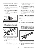
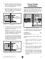
Figure 119. Example of fence aligned parallel to
miter slot.
Space
Between Blade
and Fence/Miter Slot
Even
7. Use trial-and-error to adjust the set screws
so the fence is parallel to the blade and the
clamping pressure is sufficient.
Optional: Some woodworkers prefer to off-
set the rear of the fence
1
/
64
" from the blade,
as shown in
Figure 120, to help prevent the
workpiece from binding and burning.
The argument is that this offset adjustment
reduces the chance of kickback by alleviating
potential binding that may occur between the
backside of the blade and fence. The trade-
off is slightly less accurate cuts.
Figure 120. Adjusting fence with a
1
⁄
64
" offset.
X"
X" +
1
/
64
"
Extra Space
to Prevent Binding
(Optional)
X = Your Measurement
Blade
5. Measure the distance between the fence and
the front of the blade at one end of the table
insert, then mark the tooth that you measured
from with a felt-tipped marker.
6. Rotate the blade to the other end of the
table insert (
Figure 119), and recheck the
distance between the fence and the blade to
ensure they are parallel.
Fence Scale
Calibration
The fence scale indicator window, shown in
Figure 121, can be calibrated with the fence
scale if you notice that your cuts do not accurately
match what is shown on the fence scale.
The indicator adjusts by loosening the two mount-
ing screws and sliding it in the desired direction.
Tools Needed
Qty
Hex Wrench 2.5mm ........................................... 1
Scrap Piece of Wood......................................... 1
To calibrate the fence scale indicator win-
dows:
1. Position and lock the fence at 13", as indi-
cated by the scale, cut your scrap piece of
wood.
2. Reposition and lock the fence at 12", as indi-
cated by the scale.
3. Flip your scrap piece of wood over, placing
the side that was cut in
Step 2 against the
fence, and cut your scrap piece of wood.
4. Measure the width of the freshly cut workpiece
with a tape measure. The workpiece width
should be exactly 12". If it is not, then adjust
the indicator window to match the width of the
workpiece.
Figure 121. Fence indicator window.
Screws
Indicator Window
Summary of Contents for G0690
Page 20: ...18 Model G0690 G0691 Mfd 6 15 Hardware Recognition Chart...
Page 92: ......