background image

-22-

g0665 slow speed Cold Cut saw

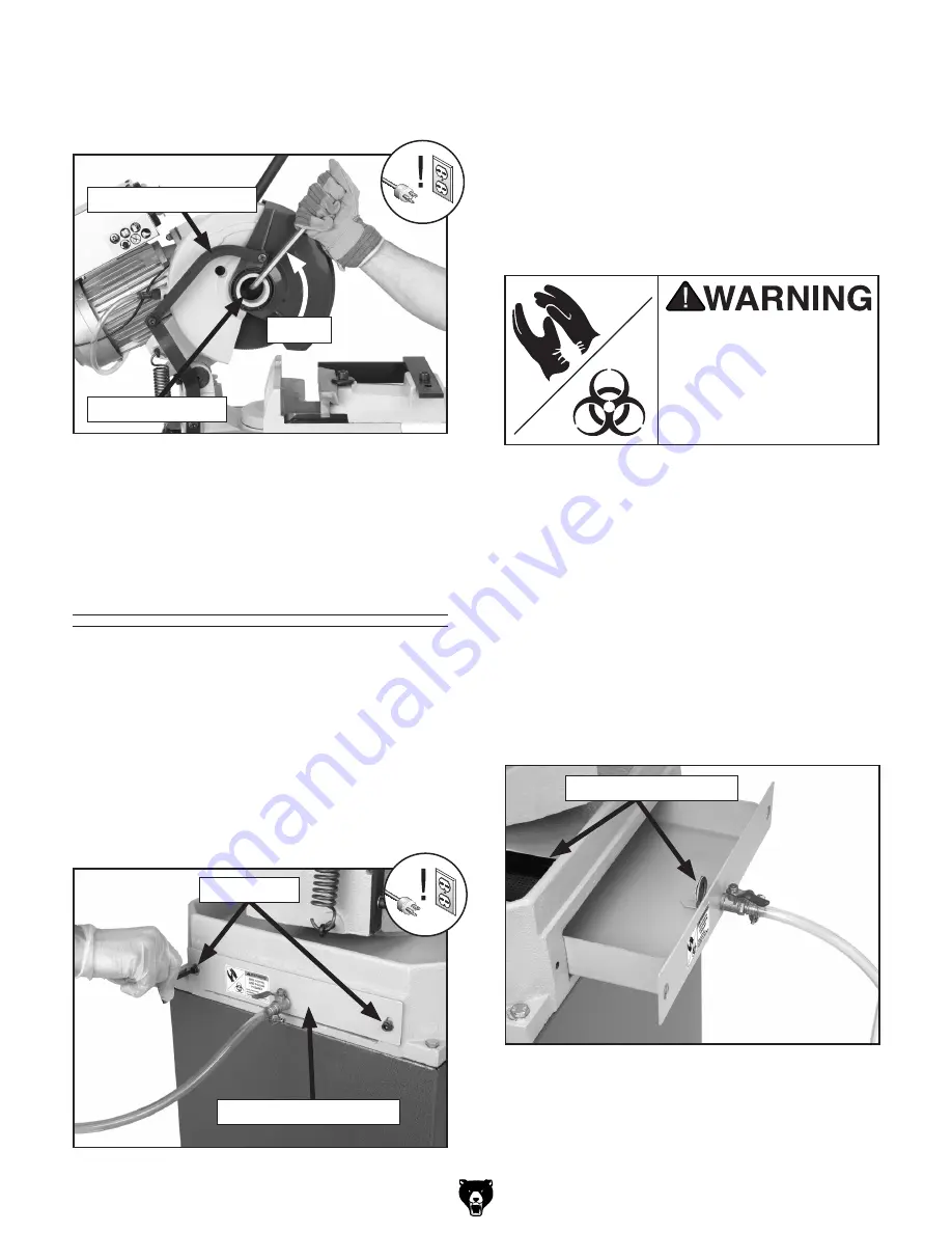
7.

  place  the  blade  and  flange  over  the  arbor, 

then  thread  and  tighten  the  left-hand  thread 
arbor cap screw (

figure 32

).

figure 32.

 tightening blade.

8.

  lower  the  blade  guide  and  reconnect  the 

blade guard linkage with the cap screw.

Cutting fluid

Tools Needed: 

Qty

hex Wrench 5mm .............................................. 1

filling the cutting fluid reservoir:

1.

  disConneCt sAW FroM poWer!

2.

  remove  the  cap  screws  and  washers  from 

the cutting fluid reservoir (

figure 33

).

Draining/cleaning  the  cutting  fluid 

reservoir:

1. 

disConneCt sAW FroM poWer!

2.

  Wearing protective equipment, drain and dis-

pose  the  cutting  fluid  following  government-
approved disposal regulations for your area.

3.

  use a rag to wipe out residual fluid.

4.

  Clean the cutting fluid screens in the machine 

base and the tank.

Used  cutting  fluid  pres-

ents  a  poison  hazard. 

Use  personal  protection 

when handling this mate-

rial. failure to do so may 

result in illness or death.

3.

  slide the tray out from the machine base.

4.

  Wearing  protective  equipment,  fill  the  reser-

voir with a suitable, water-based cutting fluid. 
refer to the manufacturer's specifications for 
the proper water/oil mix.

5.

  slide the tray back into the base and replace 

the cap screws and washers.

Arbor Cap screw

Blade guard linkage

tighten

figure 33.

 opening cutting fluid reservoir.

Cap screws

Cutting Fluid reservoir

figure 33.

 opening cutting fluid reservoir.

Cutting Fluid screens

Summary of Contents for G0665

Page 1: ...lade selection use and troubleshooting for the Model G0665 Slow Speed Cold Cut Saw Before operating your new machine you MUST read and understand the original manual AND this manual insert to reduce the risk of injury from improper use or setup If you need additional help with any of these procedures contact our Tech Support at 570 546 9663 or by email at techsupport grizzly com MODEL G0665 SLOW S...

Page 2: ...ing and rapidly rounded off teeth FIgure 3 Figure 2 TPI too coarse for workpiece Ldg e ZXZ 7aVYZ IE Idd 8dVghZ 7gd Zc Iddi I e Figure 3 TPI too fine for workpiece Ldg e ZXZ 7aVYZ IE Idd cZ mXZhh kZ 8 e 7j aYje jaaZi Selecting the right blade for the cut requires an understanding of various blade characteristics Blade Terminology A Blade Size Diameter The overall diameter of the blade The Model G06...

Page 3: ...I for standard HSS blades To select the correct blade pitch 1 Measure the thickness of your workpiece For solid workpieces this measurement is the length of cut taken from where the tooth enters the workpiece sweeps through and exits the workpiece See D on the chart in Figure 5 For hollow workpieces or profiled workpieces this measurement is the wall thickness at its thickest point Th I I I 9 3 1 ...

Page 4: ... Tight Thin Silver Good Decrease Check Blade Pitch i c XjgaZY h dgi VgY i X i X VgY higdc i X VgY higdc i c higV i edlYZgn i c XjgaZY i ian VgY i c i c XjgaZY h dgi VgY i X i X VgY higdc i X VgY higdc i c higV i edlYZgn i c XjgaZY i ian VgY i c i c XjgaZY h dgi VgY i X i X VgY higdc i X VgY higdc i c higV i edlYZgn i c XjgaZY i ian VgY i c i c XjgaZY h dgi VgY i X i X VgY higdc i X VgY higdc i c h...

Page 5: ...re for a properly broken in blade The duration of the break in period is determined by the hardness of the material cut The break in period is defined in terms of square inches of material cut For hard materials such as steel the break in period is the first 50 square inches of material cut For soft materials such as aluminum the break in period is the first 150 square inches of material cut To de...

Page 6: ...de teeth are broken missing 1 Feed speed pressure too high 2 Blade was in contact with the workpiece when machine was turned ON 3 Blade pitch incorrect for cut 4 Blade not broken in correctly 5 Insufficient blade cooling 1 Reduce feed pressure by relieving pressure on the feed lever during operation 2 Never start the blade in contact with the workpiece 3 Check blade pitch 4 Replace blade and follo...

Page 7: ......

Page 8: ......

Page 9: ...LD CUT SAW OWNER S Manual Copyright April 2008 By Grizzly Industrial Inc Warning No portion of this manual may be reproduced in any shape Or form without the written approval of Grizzly Industrial inc JB10523 printed IN TAIWAN ...

Page 10: ...PERSONAL PROTECTIVE EQUIPMENT 4HE MANUFACTURER WILL NOT BE HELD LIABLE FOR INJURY OR PROPERTY DAMAGE FROM NEGLIGENCE IMPROPER TRAINING MACHINE MODIFICATIONS OR MISUSE 3OME DUST CREATED BY POWER SANDING SAWING GRINDING DRILLING AND OTHER CONSTRUCTION ACTIVITIES CONTAINS CHEMICALS KNOWN TO THE 3TATE OF ALIFORNIA TO CAUSE CANCER BIRTH DEFECTS OR OTHER REPRODUCTIVE HARM 3OME EXAMPLES OF THESE CHEMICAL...

Page 11: ...iderations 12 Mounting to Shop Floor 13 Setup 14 Test Run 15 SECTION 4 OPERATIONS 16 Operation Safety 16 Basic Controls 16 Cutting Angle 17 Vise 18 Work Stop 20 Blade Changes 21 Cutting Fluid 22 Cutting Procedures 23 Cutting Tips 23 General Machine Tips 23 SECTION 5 ACCESSORIES 24 SECTION 6 MAINTENANCE 25 Schedule 25 Cleaning 25 Unpainted Cast Iron 25 Lubrication 25 SECTION 7 SERVICE 27 Troublesho...

Page 12: ...ss below Grizzly Industrial Inc C O Technical Documentation Manager P O Box 2069 Bellingham WA 98227 2069 Email manuals grizzly com Contact Info This Slow Speed Cold Cut Saw is used to cut metal workpieces at angles from 45 to 45 accu rately efficiently and safely The cut is adjusted to the desired angle with the integrated scale then locked with the miter lock lever The adjustable vise jaw is the...

Page 13: ...ication A Vise Handwheel B Vise Quick Release Lever C Vise D Blade Guard E Saw Lever F Trigger Switch G Power Indicator H ON OFF Switch I Cutting Fluid Pump J Work Stop K Angle Indicator Scale L Miter Lock Lever Identification A B C D E F G H I J L K ...

Page 14: ...h AZc i L Yi Z i m m 7dm IneZ 8VgYWdVgY 8dciZci HiVcY LZ i aWh AZc i L Yi Z i m m LECTRICAL Hl iX HV Zin Hl iX dc VcYaZ Hl iX KdaiV Z K 8dgY AZc i i 8dgY Vj Z Vj Z B c bjb 8 gXj i H oZ Vbe Eaj cXajYZY Cd OTOR IneZ I 8 8VeVX idg HiVgi cYjXi dc dghZedlZg E KdaiV Z K EgZl gZY K E VhZ H c aZ 6beh 6 HeZZY GEB 8nXaZ o CjbWZg D HeZZYh EdlZg IgVch Zg 9 gZXi 9g kZ 7ZVg c h H ZaYZY VcY EZgbVcZcian HZVaZY OD...

Page 15: ... m BVm bjb 8VeVX in GdjcY 5 ONSTRUCTION IVWaZ 8dchigjXi dc 8Vhi gdc HVl L ZZa 8dkZg 6ajb cjb HVl L ZZa jVgY EaVhi X 7dYn 8dchigjXi dc 8Vhi gdc 7VhZ 8dchigjXi dc 8Vhi gdc L ZZa 8dkZg 8dchigjXi dc EgZ dgbZY hiZZa EV ci edmn THER 3PECIFICATIONS HD VXidgn HD 8djcign D Dg c IV lVc LVggVcin NZVg HZg Va CjbWZg AdXVi dc BVX cZ 9 AVWZa dc 7dYn gVbZ EATURES Fj X GZaZVhZ K hZ 6jid GZigVXi 7aVYZ jVgY Heg c 6h...

Page 16: ...ETY 2EAD NSTRUCTION ANUAL EFORE PERATING THIS ACHINE 4HE PURPOSE OF SAFETY SYMBOLS IS TO ATTRACT YOUR ATTENTION TO POSSIBLE HAZARDOUS CONDITIONS 4HIS MANUAL USES A SERIES OF SYMBOLS AND SIGNAL WORDS INTENDED TO CONVEY THE LEVEL OF IMPORTANCE OF THE SAFETY MESSAGES 4HE PROGRESSION OF SYMBOLS IS DESCRIBED BELOW 2EMEMBER THAT SAFETY MESSAGES BY THEMSELVES DO NOT ELIMINATE DANGER AND ARE NOT A SUBSTIT...

Page 17: ...jXi dch dg ajWg XVi c VcY X Vc c VXXZhhdg Zh 352 5 2 3 2 0 7 2 22 4 9 2 53 29 3AFETY NSTRUCTIONS FOR ACHINERY 2 6 534 93 72 3 BV Z V VW i d X ZX c dg Znh VcY VY_jhi c lgZcX Zh WZ dgZ ijgc c bVX cZgn 2 0 243 2 53 29 8 ZX dg W cY c dg b hVa cZY eVgih Wgd Zc eVgih addhZ Wdaih VcY Vcn di Zg XdcY i dch i Vi bVn beV g bVX cZ deZgVi dc GZeV g dg gZeaVXZ YVbV ZY eVgih WZ dgZ deZgVi dc 53 2 33 2 3 GZ Zg id...

Page 18: ...y worn blade Inspect blades for cracks and missing teeth before each use 2 HAND PLACEMENT Never position fin gers or thumbs in line with the cut Hands could be crushed in vise or from falling machine components 3 ENTANGLEMENT HAZARDS Do not operate this saw without blade guard in place Loose clothing jewelry long hair and work gloves can be drawn into working parts 4 BLADE REPLACEMENT When replac ...

Page 19: ... properly connected to the grounding prong on the plug likewise the outlet must be properly installed and grounded All electrical connections must be made in accor dance with local codes and ordinances Amperage Draw The Model G0665 motor draws the following amps under maximum load Motor Draw 6 Amps Power Supply Circuit Requirements We recommend connecting your machine to a dedicated and grounded c...

Page 20: ...ted Min 300 lbs Optional 1 Wrench 13mm 1 Ratchet Socket 13mm 1 Hex Wrench 5mm 1 Items Needed for Setup Your machine was carefully packaged for safe transportation Remove the packaging materials from around your machine and inspect it If you discover the machine is damaged please imme diately call Customer Service at 570 546 9663 for advice Save the containers and all packing materials for possible...

Page 21: ...mponents for shipping purposes Container 1 Figure 3 Qty A Saw 1 B Work Stop Rod 1 C Work Stop 1 Container 2 Figure 4 D Stand Rear Panel 1 E Stand Side Panels 2 F Stand Front Panel 1 Hardware Not Shown Hex Bolts M8 1 25 x 20 Stand 12 Hex Nuts M8 1 25 Stand 12 Hex Bolts M8 1 25 x 35 Saw Mounting 4 Figure 3 Machine inventory If any nonproprietary parts are missing e g a nut or a washer we will gladly...

Page 22: ...painted surfaces are coated with a waxy oil to prevent corrosion during shipment Remove this protective coating with a solvent cleaner or degreaser shown in Figure 5 For thorough cleaning some parts must be removed For opti mum performance from your machine clean all moving parts or sliding contact surfaces Avoid chlorine based solvents such as acetone or brake parts cleaner that may damage painte...

Page 23: ...fasteners for mounting to concrete floors NOTICE We strongly recommend securing your machine to the floor if it is hardwired to the power source Consult with your electrician to ensure compliance with local codes Once the stand is assembled see Setup on Page 14 it is ready to be mounted to the shop floor To mount the stand to the floor 1 Drill four holes in the inner lip at the bottom of the stand...

Page 24: ...do so now see Mounting to Shop Floor on Page 13 then return to Step 4 below to mount the machine to the stand Otherwise continue with Step 4 below Figure 9 Front and side panels 2 Attach the remaining side panel in the same manner as Step 1 as shown in Figure 10 Figure 10 Second side panel attached Front Panel Side Panel Side Panel 4 Place the saw onto the stand and secure it with the four M8 1 25...

Page 25: ... sure all tools and objects used during setup are cleared away from the machine 4 Connect the machine to the power source 5 Turn the machine ON 6 Listen to and watch for abnormal noises or actions The machine should run smoothly with little or no vibration or rubbing noises Strange or unusual noises should be inves tigated and corrected before operating the machine further Always disconnect the ma...

Page 26: ... get formal training before begin ning any projects Regardless of the con tent in this section Grizzly Industrial will not be held liable for accidents caused by lack of training Operation Safety Basic Controls Use the descriptions and figures below to become familiar with the basic controls of your machine ON OFF Switch Turns main power to the machine ON OFF Power Indicator Light Glows green when...

Page 27: ...ity bracket to pro vide adequate clearance as outlined in Vise on Page 18 5 Return the saw to the upright position Cutting Angle Saw Lever Lowers the saw into the workpiece Trigger Switch Turns the motor ON spinning the blade and activating the cutting fluid pump Miter Lock Lever Releases or locks rotation of the saw base for angled cuts Work Stop Set at a particular distance from the blade to pro...

Page 28: ...bed above If this is the case adjust the jaw as far as it can go while still being securely clamped Cap Screw Vise Jaw Figure 21 Setting blade clearance Jaw 1 2 Gap Blade To adjust the vise jaw 1 DISCONNECT SAW FROM POWER 2 Set the cutting angle as described in Cutting Angle on Page 17 3 Lower the saw to check for clearance If the saw blade lowers completely without touching the vise jaw or stabil...

Page 29: ...than 30 away from the vise it is necessary to remove the auxil iary stability bracket entirely Vise Quick Release Lever For repetitive cutting procedures that require frequent clamping and unclamping of the same size stock the Model G0665 is equipped with a quick release lever that allows the workpiece to be released repositioned then quickly reclamped To use the quick release lever 1 DISCONNECT S...

Page 30: ...ver in this position fully clamp the workpiece using the vise handwheel To release the workpiece rotate the lever clockwise to the up position The method you practice is a matter of personal preference Clamped Released 3 Lower the blade as far as it will go 4 Measure from the side of the blade to the work stop Slide the work stop until the dis tance between the blade and the work stop is equal to ...

Page 31: ... teeth of saw blades are sharp and can easily cut fingers and hands Always wear heavy leath er gloves when handling saw blades To replace the blade 1 DISCONNECT SAW FROM POWER 2 Disconnect the blade guard linkage by remov ing the cap screw that connects it to the saw guard Figure 28 3 Rotate the blade guard and linkage out of the way as shown in Figure 29 Figure 29 Exposing blade Figure 28 Removin...

Page 32: ...uid following government approved disposal regulations for your area 3 Use a rag to wipe out residual fluid 4 Clean the cutting fluid screens in the machine base and the tank Used cutting fluid pres ents a poison hazard Use personal protection when handling this mate rial Failure to do so may result in illness or death 3 Slide the tray out from the machine base 4 Wearing protective equipment fill ...

Page 33: ...de lower the saw into the workpiece Use a controlled steady force to complete the cut When the cut is completed raise the saw release the trigger and allow the blade to come to a complete stop before proceeding Cutting Tips Replace sharpen and clean blades as nec essary to maintain optimum cutting perfor mance Use even pressure while cutting Heavy or irregular pressure can lead to poor cuts and da...

Page 34: ...48 Economy Clear Safety Glasses T20452 Kirova Anti Reflective Glasses T20456 Dakura Clear Safety Glasses H0736 Shop Fox Safety Glasses These glasses meet ANSI Z87 1 2003 specifica tions Buy extras for visitors or employees You can t be too careful with shop safety Figure 36 Our most popular eye protection T20448 H0736 T20452 T20501 T20456 G8983 Tilting Roller Stand Adjusts from 26 to 44 0º 45º 150...

Page 35: ... Oil the main saw hinge pin Every Six Months Change gearbox oil Schedule Cleaning the Model G0665 is relatively easy Vacuum excess metal chips and wipe off the remaining debris and cutting fluid residue with a dry cloth Cleaning Protect the unpainted cast iron surfaces on the machine by wiping the table clean after every use this ensures moisture from wood dust does not remain on bare metal surfac...

Page 36: ... SAE 30WT oil into the hole in the back of the hinge pin housing Figure 38 Figure 38 Oil change 4 Wait several minutes for the oil to spread then raise and lower the saw repeatedly to distribute the oil 5 Wipe any excess oil from the machine Oil Hole 4 Hold the drain pan under the oil fill drain plug then tilt the saw forward and allow all of the oil to drain out 5 Raise the saw back to the up mos...

Page 37: ...ly has the correct voltage 7 Check for broken wires or disconnected corroded connections and repair replace as necessary 8 Replace faulty ON OFF switch 9 Test repair replace Machine stalls or is overloaded 1 Feed pressure too great for task 2 Motor connection is wired incorrectly 3 Plug receptacle is at fault 4 Motor is at fault 1 Decrease feed pressure 2 Correct motor wiring connections 3 Test fo...

Page 38: ...correct source of machine vibration 4 Lower blade in a slow and controlled manner Vibration when cutting 1 Wrong tooth pitch profile 2 Workpiece is not secured in vise 3 Cross section of workpiece is too large 1 Use correct blade 2 Secure workpiece 3 Adhere to maximum cutting capacities for this machine Cut is not straight 1 Cutting pressure is too high 2 Workpiece is not secured in vise 3 Cutting...

Page 39: ...G0665 Slow Speed Cold Cut Saw 29 Electrical Components Figure 40 G0665 electrical components Contactor Transformer Overload Relay ON OFF Switch 15A Fuses Start Capacitor Indicator Light ...

Page 40: ...time of printing but it may not match your machine Always use the wiring diagram inside the motor junction box 220 VAC 6 15 Plug As Recommended di di gdjcY A A CD I I 8DCI68IDG I C9 K I CD CD CD C8 C8 I I I G H I A TC 11 IG6CH DGB G Gjc 8VeVX idg B 9 K68 ID BDIDG EDL G C9 86IDG IG G HL I8 DC D HL I8 gdjcY gdjcY A E A A A B CD C8 8DB 6 6 K K K K DK GAD69 G A6N I C9 I G 6G8 Wiring Diagram ...

Page 41: ...29 30 31 31 31 31 33 34 35 36 37 37 38 39 40 41 42 101 1 101 4 102 103 101 3 101 12 101 13 101 2 101 5 101 6 101 11 101 10 101 9 101 8 101 7 101 43 44 45 46 47 47 48 49 50 51 52 53 54 55 56 57 58 58 59 60 61 62 63 64 65 66 67 68 79 82 85 86 86 1 86 2 87 88 89 90 91 92 93 94 97 98 100 101 14 Parts Breakdown ...

Page 42: ... 20 P0665020 LEADSCREW 89 PSB16M CAP SCREW M4 7 X 16 21 P0665021 AUXILIARY STABILIZING BRACKET 90 P0665090 COOLANT PUMP 29 P0665029 COOLANT TRAY 91 PSB02M CAP SCREW M6 1 X 20 30 P0665030 COOLANT VALVE 92 P0665092 OIL LEVEL DRAIN PLUG 31 P0665031 COOLANT TUBE 93 P0665093 WORM SCREW 33 P0665033 TANK FILTER 94 P0665094 HEAD GASKET 34 P0665034 FLAT HD SCR M8 1 25 X 20 97 PW01M FLAT WASHER 8MM 35 P0665...

Page 43: ...own REF PART DESCRIPTION REF PART DESCRIPTION 201 P0665201 END PANEL 206 PB09M HEX BOLT M8 1 25 X 20 202 P0665202 SIDE PANEL 207 G8589 GRIZZLY NAMEPLATE LARGE 203 PB20M HEX BOLT M8 1 25 X 35 208 PHTEK24 TAP SCREW 5 X 3 8 205 PN03M HEX NUT M8 1 25 ...

Page 44: ...chine again Contact Grizzly at 800 523 4777 or www grizzly com to order new labels REF PART DESCRIPTION REF PART DESCRIPTION 301 P0665301 MACHINE ID LABEL 306 PLABEL 14 ELECTRICITY LABEL 302 P0665302 AMPUTATION HAZARD LABEL 307 P0665307 CUTTING FLUID LABEL 303 P0665303 EYE INJURY LABEL 308 P0665308 MODEL NUMBER LABEL 304 P0665304 READ MANUAL LABEL 309 PPAINT 1 GRIZZLY GREEN TOUCH UP PAINT 305 P066...

Page 45: ...TT TTTT TTTT TTTT TTTT L Vi h ndjg V Z gdje4 TTTT TTTT TTTT TTTT TTTT TTTT dl adc VkZ ndj WZZc V lddYldg Zg bZiValdg Zg4 TTTT NZVgh TTTT NZVgh TTTT NZVgh TTTT NZVgh dl bVcn d ndjg bVX cZh dg iddah VgZ g ooan4 TTTT TTTT TTTT TTTT 9d ndj i c ndjg bVX cZ gZegZhZcih V ddY kVajZ4 TTTTTNZh TTTTTCd LdjaY ndj gZXdbbZcY g ooan cYjhig Va id V g ZcY4 TTTTTNZh TTTTTCd LdjaY ndj Vaadl jh id jhZ ndjg cVbZ Vh V ...

Page 46: ...DI HI6EA DA9 6ADC 9DII 9 A C DA9 6ADC 9DII 9 A C 2 9 5342 0 8 7 EaVXZ HiVbe ZgZ CVbZTTTTTTTTTTTTTTTTTTTTTTTTTTTTTTT HigZZiTTTTTTTTTTTTTTTTTTTTTTTTTTTTTTT 8 inTTTTTTTTTTTTTTHiViZTTTTTTO eTTTTTT HZcY V g ooan 8ViVad id V g ZcY ...

Page 47: ...n h Vaa WZ ig ZY c i Z HiViZ d LVh c idc 8djcin d L ViXdb LZ h Vaa c cd ZkZci WZ a VWaZ dg YZVi c_jg Zh id eZghdch dg egdeZgin dg dg cX YZciVa Xdci c Zci heZX Va dg XdchZfjZci Va YVbV Zh Vg h c gdb i Z jhZ d djg egdYjXih Id iV Z VYkVciV Z d i h lVggVcin XdciVXi jh Wn bV a dg e dcZ VcY kZ jh Vaa i Z YZiV ah LZ l aa i Zc hhjZ ndj V GZijgc CjbWZg l X bjhi WZ XaZVgan edhiZY dc i Z djih YZ Vh lZaa Vh i...

Page 48: ...IRECT AND 3AVE WITH RIZZLY n 4RUSTED 0ROVEN AND A REAT 6ALUE 2 s 3 52 2 2 s 2 23 3 00 7 4 523 s 2 30 3 7 4 52 6ISIT UR 7EBSITE 4ODAY ND ISCOVER 7HY RIZZLY S 4HE NDUSTRY EADER ALL 4ODAY OR 2 ULL OLOR ATALOG ...

Reviews: